
-
Filter By Stock
- In Stock (6)
Filter By Brand
- iduino (8)
Arduino Relay Modules
Popular Products


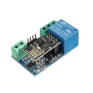
Arduino Relay Modules
What Is an Arduino Relay Module?
An Arduino relay module is an electronic switching device that allows a microcontroller to control external electrical circuits. It uses an electrically operated relay to switch connected devices on or off in response to control signals from an Arduino development board or another compatible microcontroller.
Relay modules are commonly used in electronics projects that require automated switching, allowing low-voltage control circuits to operate separate electrical loads. They are available in different configurations, including single-channel, dual-channel and four-channel relay boards.
Arduino relay modules are popular for home automation, lighting control, robotics, industrial prototyping and other electronic applications. They provide a convenient way to integrate programmable switching into DIY electronics and automation projects.
How Does an Arduino Relay Module Work?
An Arduino relay module works by receiving a control signal from a microcontroller and using that signal to activate an electrically operated switching mechanism.
When the relay receives the appropriate input signal, its internal contacts change position, allowing the connected circuit to be switched on or off.
Most mechanical relay modules include three main contact terminals:
-
COM (Common): The shared electrical connection for the switching contacts.
-
NO (Normally Open): The circuit is disconnected when the relay is inactive and connects when the relay is activated.
-
NC (Normally Closed): The circuit is connected when the relay is inactive and disconnects when the relay is activated.
The Arduino controls the relay through a digital output connected to the module's input circuit. Many relay boards also include driver transistors, status LEDs and protective circuitry to simplify integration with microcontrollers.
Types of Arduino Relay Modules
Arduino relay modules are available in different configurations to suit various electronics and automation requirements.
1. Single-Channel Relay Modules
Single-channel relay modules contain one relay and allow an Arduino to control one external electrical circuit. They are suitable for simple switching applications such as lighting control, small pumps and electronic devices.
2. Dual-Channel Relay Modules
Dual-channel relay modules provide two independently controlled relays on one circuit board. They are useful for projects requiring two separate switching outputs, such as controlling multiple lights or automation devices.
3. Four-Channel Relay Modules
Four-channel relay modules contain four independently controlled relays, allowing an Arduino to operate multiple electrical circuits. They are suitable for home automation, multi-output control systems and electronics projects requiring several switching channels.
4. Solid-State Relay Modules
Solid-state relay modules use semiconductor switching components rather than mechanical contacts. They have no moving mechanical parts and are useful for applications requiring silent operation and frequent switching. Their load compatibility depends on whether the module is designed for AC or DC switching.
5. USB-Controlled Relay Modules
USB-controlled relay modules allow switching operations to be controlled through a computer or compatible USB interface. They are useful for computer-controlled automation, testing equipment and programmable switching applications.
6. Wi-Fi Relay Modules
Wi-Fi relay modules provide wireless control capabilities for compatible automation projects. They can be integrated into network-connected systems to enable remote switching and Internet of Things (IoT) applications.
5V vs 12V Arduino Relay Modules
Arduino relay modules are commonly available with different operating voltage requirements. The two common configurations are 5V and 12V relay modules.
|
Feature |
5V Relay Module |
12V Relay Module |
|---|---|---|
|
Relay coil voltage |
5V |
12V |
|
Typical application |
5V control systems |
12V control systems |
|
Power supply |
Compatible regulated 5V supply |
Compatible regulated 12V supply |
|
Arduino integration |
Requires compatible input circuitry |
Requires compatible input circuitry |
|
Common uses |
Electronics and automation |
Industrial-style and 12V automation projects |
The main difference is the voltage required to operate the relay coil. A 5V Arduino relay module is often convenient for projects using 5V control systems, while a 12V module is suitable when a compatible 12V supply is available.
Importantly, the relay coil voltage is not necessarily the same as the input logic voltage. Always check the individual module's specifications before connecting it to an Arduino.
Single-Channel vs Multi-Channel Relay Boards
Choosing between single-channel and multi-channel relay modules depends on how many independent electrical circuits your project needs to control.
|
Feature |
Single-Channel |
Dual-Channel |
Four-Channel |
|---|---|---|---|
|
Number of relays |
1 |
2 |
4 |
|
Independent outputs |
1 |
2 |
4 |
|
Control connections |
Typically 1 input |
Typically 2 inputs |
Typically 4 inputs |
|
Typical application |
One device |
Two devices |
Multiple devices |
|
Installation |
Compact |
Moderate |
Larger board |
Single-channel modules are suitable for simple switching tasks, while multi-channel boards provide more flexibility for complex automation projects.
Mechanical Relays vs Solid-State Relays
Mechanical and solid-state relays both perform electrical switching, but they use different technologies.
|
Feature |
Mechanical Relay |
Solid-State Relay |
|---|---|---|
|
Switching technology |
Electromechanical contacts |
Semiconductor components |
|
Moving parts |
Yes |
No |
|
Operating noise |
May produce a clicking sound |
Silent |
|
Switching speed |
Generally slower |
Generally faster |
|
Contact wear |
Contacts can wear over time |
No mechanical contact wear |
|
Leakage current |
Generally very low when open |
Can have off-state leakage |
|
Applications |
General electrical switching |
Frequent or silent switching |
Mechanical relays are commonly used for general-purpose switching, while solid-state relays are useful for applications requiring silent operation or frequent switching.
When selecting a solid-state relay, check the AC or DC switching type, minimum load requirements, voltage rating and heat dissipation requirements.
Technical Specifications to Consider When Choosing an Arduino Relay Module
Before purchasing an Arduino relay module, consider these important specifications:
-
Operating Voltage: Check the voltage required to power the relay coil and module electronics.
-
Input Logic Voltage: Confirm that the control input is compatible with your Arduino board.
-
Number of Channels: Choose the number of independently controlled outputs required.
-
Switching Current: Check the maximum current supported by each relay contact.
-
Switching Voltage: Confirm the supported AC or DC voltage for the connected load.
-
Contact Configuration: Check whether the relay provides SPDT, SPST or another contact arrangement.
-
Isolation: Look for suitable electrical isolation between control and load circuits where required.
-
Mounting Options: Consider mounting holes, screw terminals and enclosure requirements.
-
Switching Frequency: Consider the expected operating frequency and relay lifetime.
-
Load Type: Check whether the module is suitable for resistive, inductive or other load types.
For example, the listed iDuino four-channel 5V relay module (TA0045a) features four SPDT relays, status LEDs, active-high logic and screw terminals. Its published contact ratings are 10A at 250VAC and 10A at 30VDC per channel. Actual suitability depends on the load type and installation conditions.
What Can You Control with an Arduino Relay Module?
Arduino relay modules can be used in many electronics and automation projects where programmable electrical switching is required.
Common applications include:
-
Lighting Control: Switch compatible lighting circuits using programmed control signals.
-
Home Automation: Build systems for automated switching of household devices.
-
Water Pumps: Control compatible pumps in irrigation and water management projects.
-
Cooling Fans: Switch fans and ventilation equipment in automated systems.
-
Robotics: Control auxiliary electrical devices and external systems.
-
Security Projects: Integrate switching functions into access control and alarm prototypes.
-
Industrial Prototyping: Develop automated control systems for testing and demonstration.
-
IoT Applications: Combine Wi-Fi relay modules with network-connected automation systems.
How to Connect a Relay Module to an Arduino
Connecting a compatible relay module to an Arduino involves linking the module's control inputs and power connections to the development board.
A typical low-voltage connection uses:
-
VCC: Connect to the module's specified supply voltage.
-
GND: Connect to the appropriate common ground where required by the module design.
-
IN: Connect the relay control input to a compatible Arduino digital output.
-
COM: Connect the common relay contact to the external circuit.
-
NO or NC: Select the normally open or normally closed contact depending on the required switching behaviour.
A basic Arduino program can then activate the relay using a digital output:
const int relayPin = 7;
void setup() {
pinMode(relayPin, OUTPUT);
digitalWrite(relayPin, LOW);
}
void loop() {
digitalWrite(relayPin, HIGH);
delay(2000);
digitalWrite(relayPin, LOW);
delay(2000);
}
This example assumes an active-high relay module. Some modules use active-low inputs, so the control logic must be adjusted to match the manufacturer's specifications.
Electrical safety: Use low-voltage DC loads when learning to connect relay modules. Mains-voltage circuits can cause electric shock, fire or serious injury. Mains installations should use appropriately rated equipment, enclosures and protection and be completed by a licensed electrician in accordance with applicable Australian requirements. Never assume that an Arduino relay module is safe for mains switching simply because a contact rating is printed on it.
How to Choose the Right Arduino Relay Module
Choosing the right relay module depends on your project's switching requirements and electrical specifications.
-
For simple switching: Choose a single-channel relay module.
-
For two independent devices: Consider a dual-channel relay board.
-
For multiple switching outputs: Choose a four-channel relay module.
-
For 5V electronics: Select a compatible 5V relay module.
-
For 12V control systems: Consider a suitable 12V relay module.
-
For silent switching: Investigate a compatible solid-state relay.
-
For computer control: Consider a USB-controlled relay module.
-
For wireless automation: Choose a compatible Wi-Fi relay module.
Always check the relay's contact ratings, input requirements and compatibility with the connected equipment before purchasing.
Arduino Relay Modules – Frequently Asked Questions
1. What is an Arduino relay module?
An Arduino relay module is an electronic board that allows an Arduino microcontroller to switch electrical circuits on and off. It typically includes one or more relays, driver circuitry and connection terminals. Relay modules are available in different configurations, including 5V, 12V, single-channel and multi-channel models.
2. What is an Arduino relay board used for?
An Arduino relay board is used to control electrical devices through an Arduino program. Common applications include home automation, lighting control, pumps, fans, motors, alarms and other electronic projects. It allows a low-voltage microcontroller to control a separate electrical circuit without directly powering the connected device.
3. How does an Arduino relay module work?
An Arduino sends a digital HIGH or LOW signal to the relay module's input. The module's driver circuit activates the relay coil, causing its internal contacts to change position and open or close the connected circuit. This allows the Arduino to control a separate load while keeping the control circuit electrically separate from the switched circuit in appropriately designed modules.
4. What is the difference between a 5V and 12V relay module?
The main difference is the voltage required to operate the relay coil and, depending on the design, the module's control circuitry. A 5V relay module is commonly used with Arduino boards that provide 5V logic, while a 12V relay module generally requires a separate 12V supply for its relay circuitry. Always check the module's input voltage and logic requirements, as a 12V relay module does not necessarily accept a 12V control signal.
5. What is the difference between single-channel and four-channel relay modules?
A single-channel relay module contains one relay and can control one independent electrical circuit. A four-channel relay module contains four relays, allowing an Arduino to control up to four separate circuits. Four-channel boards are useful for projects involving multiple lights, fans, pumps or other electrical devices.
6. How many relays can an Arduino control?
An Arduino can control multiple relays, with the practical number depending on the board's available digital output pins, power capacity and the relay module's electrical requirements. A typical four-channel relay board uses four control pins, although some modules support alternative control methods. For larger projects, consider using relay expansion boards, I/O expanders or dedicated controllers.
7. Can an Arduino control a 12V relay?
Yes. An Arduino can control a 12V relay module provided it has compatible input circuitry. The relay coil usually requires a separate 12V power supply, while the Arduino provides the control signal. Do not connect a 12V relay coil directly to an Arduino output pin, as Arduino pins are not designed to supply that voltage or the required coil current.
8. How do I connect a relay module to an Arduino?
A typical relay module connects to an Arduino through three control connections: VCC, GND and IN. Connect the module's VCC and GND to the appropriate supply connections, then connect IN to a compatible Arduino digital output pin. For multi-channel modules, each relay generally has its own input pin. Follow the manufacturer's wiring diagram and power requirements, and use a suitable external supply if necessary.
9. How do I program an Arduino relay module?
An Arduino relay module can be programmed using the Arduino IDE and the digitalWrite() function to switch its input pin between HIGH and LOW. For example, the following basic sketch switches a relay on for two seconds and then off for two seconds.
const int relayPin = 7;

void setup() {
  pinMode(relayPin, OUTPUT);
}

void loop() {
  digitalWrite(relayPin, HIGH); // Relay ON
  delay(2000);

  digitalWrite(relayPin, LOW);  // Relay OFF
  delay(2000);
}
This example assumes an active-high relay module. Some modules are active-low, meaning LOW switches the relay on and HIGH switches it off. Check the module's documentation before uploading your code.
10. What is the difference between normally open and normally closed relay contacts?
Normally open (NO) contacts remain disconnected when the relay is not energised and connect when the relay activates. Normally closed (NC) contacts remain connected when the relay is not energised and disconnect when the relay activates. The choice depends on whether the connected device should normally be off or on when the relay is inactive.
11. What does COM, NO and NC mean on a relay?
These labels identify the three main terminals of a single-pole double-throw relay:
-
COM (Common): The shared contact that switches between NO and NC.
-
NO (Normally Open): Connects to COM when the relay is energised.
-
NC (Normally Closed): Connects to COM when the relay is not energised.
These terminals provide flexibility when designing circuits that need to switch between connected and disconnected states.
12. What is the difference between mechanical and solid-state relay modules?
Mechanical relay modules use an electromagnetic coil and physical contacts to switch a circuit. They can handle many different AC and DC loads but have moving parts that wear over time and may produce an audible clicking sound. Solid-state relay (SSR) modules use semiconductor components instead of mechanical contacts, allowing silent switching and potentially faster operation. Their compatibility, leakage current, heat dissipation and load requirements differ, so check the specifications before selecting one.
13. Can an Arduino relay module control AC appliances?
Yes, a suitably rated relay module can switch compatible AC appliances, provided its contact voltage and current ratings are appropriate for the load. However, working with mains electricity presents a serious risk of electric shock and fire. In Australia, mains wiring and installation should be undertaken by a licensed electrician using appropriate enclosures, insulation and electrical protection. A relay's stated contact rating alone does not guarantee that an assembled module is safe for mains use.
14. Can an Arduino relay module control DC motors?
Yes. An Arduino relay module can switch a compatible DC motor on and off, provided the relay contacts are rated for the motor's voltage, running current and starting or stall current. Motors can produce electrical interference and voltage spikes, so suitable suppression components may be required. For speed control or frequent direction changes, a dedicated motor driver is generally more suitable than a standard relay module.
15. What is the maximum current an Arduino relay module can switch?
The maximum switching current depends on the relay and the module's design. For example, some four-channel relay modules specify contact ratings of up to 10A at 250V AC or 10A at 30V DC per channel. These ratings are not interchangeable: the permitted current depends on the voltage, load type and switching conditions. Inductive loads such as motors may require a lower rating, and the PCB tracks, terminals and wiring must also be suitable for the load.
16. Do Arduino relay modules require an external power supply?
Not always. Some small relay modules can operate from an Arduino's 5V supply, provided the board can safely supply the required current. Multi-channel modules and 12V relay boards commonly require a separate power supply. Check the module's current requirements and wiring instructions, and ensure that any shared control connections use the correct grounding arrangement.
17. What is an optically isolated Arduino relay module?
An optically isolated relay module uses an optocoupler to transfer control signals between the Arduino input circuit and the relay driver circuit using light. This can help reduce electrical noise and provide isolation between circuit sections. However, actual isolation depends on the module's design, PCB layout, power connections and wiring. Optical isolation should not automatically be treated as proof that a module is suitable for mains applications.
18. Can I control an Arduino relay module using Wi-Fi?
Yes. An Arduino-compatible Wi-Fi board, such as an ESP8266 or ESP32-based controller, can operate a compatible relay module through a wireless connection. This makes it possible to control lights, appliances and other devices through a web interface, smartphone application or home automation system. Check the controller's logic voltage and the relay module's input requirements to ensure compatibility.
19. What is the difference between a USB relay module and an Arduino relay module?
A USB relay module connects directly to a computer through a USB port and is generally controlled using computer software or commands. An Arduino relay module is typically controlled through the digital output pins of an Arduino or another compatible microcontroller. Some USB relay modules can also be incorporated into microcontroller projects, but their communication methods and software requirements may differ.
20. What should I consider when choosing an Arduino relay module?
Consider the following factors when selecting an Arduino relay module:
-
Operating voltage: Choose a 5V or 12V module that suits your power supply and control setup.
-
Number of channels: Select single-channel, two-channel or four-channel boards according to how many circuits you need to control.
-
Contact ratings: Check the maximum switching voltage and current for your particular AC or DC load.
-
Relay type: Choose between mechanical relays and solid-state relays based on switching speed, noise, load compatibility and expected service life.
-
Isolation: Consider optically isolated modules where electrical noise reduction or circuit separation is important.
-
Control compatibility: Check whether the module uses active-high or active-low inputs and whether it is compatible with your Arduino board's logic voltage.
-
Power requirements: Determine whether the module can use the Arduino supply or needs a separate power source.
-
Applications: Consider whether you are controlling lights, motors, pumps, appliances or other electrical equipment.
Choosing a relay module with suitable electrical ratings and compatible control requirements helps ensure reliable operation in Arduino automation and electronics projects.
