
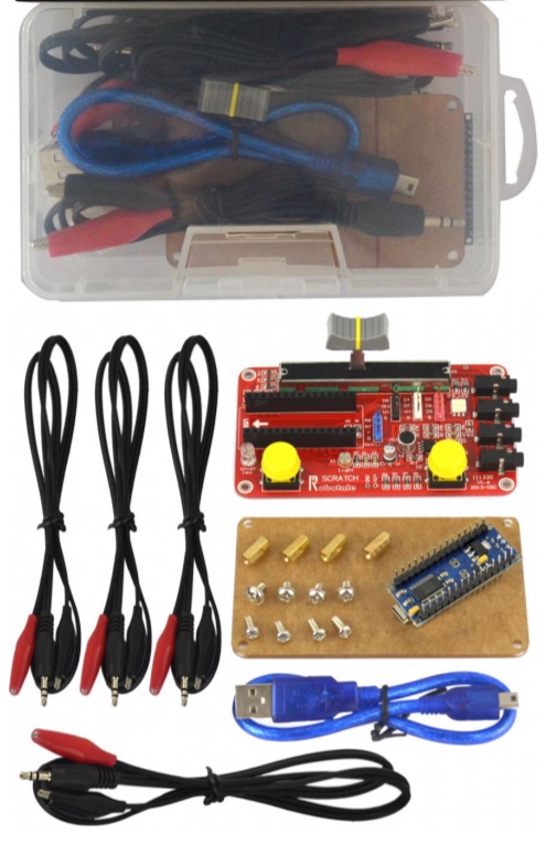
TA0015 Nano Scratch Starter Kit for Arduino Projects
Author: Aus Electronics Direct Date Posted:9 August 2019
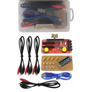
TA0015 Nano Scratch Starter Kit for Arduino Projects
S4A is a Scratch modification that allows for simple programming of the Arduino open source hardware platform. It provides new blocks for managing sensors and actuators connected to Arduino development boards.
Refer to http://s4a cat for more information about the Scratch for Arduino programming environment. You can download a version of S4A for Windows, Macintosh, Linux (Debian), Linux (Fedora), or Linux (Raspbian). The S4A site also provides links back to the Arduino.cc site as well as firmware needed for your Arduino board. See below for information on your Nano specifications and pin out, as well as where to locate the Arduino Integrated Development Environment (IDE) that is referenced in the examples.
Specifications:
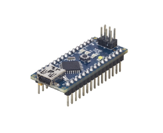
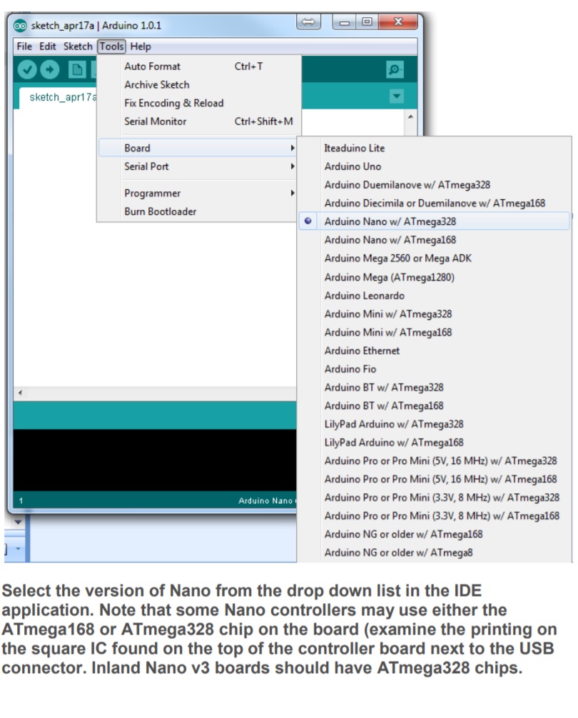
Microcontroller: Atmel ATmega168 or ATmega328
Operating Voltage (logic level): 5 V
Input Voltage (recommended): 7-12 V
Input Voltage (limits): 6-20 V
Digital I/O Pins: 14 (of which 6 provide PWM output)
Analog Input Pins: 8
DC Current per I/O Pin: 40 mA
Flash Memory: 16 KB (ATmega168) or 32 KB (ATmega328)
SRAM: 1 KB (ATmega168) or 2 KB (ATmega328)
EEPROM: 512 bytes (ATmega168) or 1 KB (ATmega328)
Clock Speed: 16 MHz
Dimensions: 0.73" x 1.70"
Length: 45 mm
Width: 18 mm
Weight: 5 g
See http://arduino.cc for detailed specifications, overviews, schematics, etc. Core functions, code examples, and links to many of the device libraries can be found in the learning section; refer to the manufacturer's site if using other add-on shields or sensors.
The latest Arduino Integrated Development Environment (IDE) necessary for programming your Nano r3 board can be obtained at http://arduino.cc/en/Main/Software (the Download menu choice on Arduino.cc)
Examples for many basic components can be found under the Examples menu. As you install libraries for additional shields, new examples may be available.
Follow the getting started guide found on the arduino.cc web site. Click Learning and select Getting started. Click on the link for Windows, Mac OS X, or Linux for more specific directions.
Getting Started:
1. Download the Arduino Environment (IDE) and install or unzip/extract the application directory.
2. Connect the Nano r3 board to one of your computer's USB port.
3. Install the drivers (If the computer does not automatically download and install the necessary USB drivers, point the hardware setup to the "drivers" directory of the Arduino IDE application.)
4. Launch the Arduino IDE application
5. Open a sketch example such as "Blink"
6. Select your Board from the Tools menu.
7. Select the Serial Port used by the board
8. Upload the sketch to the board
Sketch (code) Examples are included as part of the IDE. If you install device libraries for other components or shields, additional examples may be included and will show up in the list under the IDE File menu. (See: http://arduino.cc/en/Tutorial/HomePage for an overview of the core functions and libraries.)
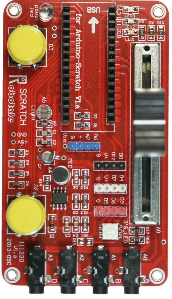
Robotale Scratch shield for Arduino Nano
The scratch shield incorporates multiple sensors and components that can be directly addressed by an Arduino Nano controller when it is installed in the socket on the shield. When the Arduino is installed and power is supplied through the mini-USB connection, the "power LED" will be illuminated in addition to those on the Nano itself. (Our board has a flashing, multi-colour LED which cycles through the RGB colours combinations.)
Addressable Components include:
Large button switches (2) connected to pins D2 and D3. The connection is Normally Open (off) until the button is pushed.
To use the Arduino example sketch "Button", configure your IDE board to Arduino Nano with the appropriate COM port, and then load the "Button" sketch:
File, Examples, 02.Digital, Button
The default configuration in this sketch is set to use a button switch on D2 and the LED on D13. Upload the sketch as is to use the button switch furthest from the Nano. When you press the button, both the LED on the Nano board and the surface mount LED on D13 should light up.
In the Button sketch, change buttonPin = 2 to buttonPin = 3 to use the switch closest to the Nano. Change ledPin = 13 to ledPin = 11, ledPin = 10, ledPin = 9, ledPin = 6, or to ledPin = 5 to illuminate one of the other LEDs on the shield.
(Surface mount LED pins and the RGB pins are detailed below...)
Slide Potentiometer (2.5K ohms) connected to pin A0
You can test the slide potentiometer by loading the basic code example "ReadAnalogVoltage" which detects a change in voltage on analog pin 0 and "prints" the value to the serial port. To view the result, Use the IDE to upload the sketch to the Nano. Once this has been done, open the serial monitor from the IDE Tools Menu (or press control-shift-M). You should see a stream of voltage values between 0.00 and 5.00 as you move the slider back and forth.
Load this example sketch in the IDE from:
File, Examples, 01.Basics, ReadAnalogVoltage
Photo resistor connected to pin A5
You can test the photo resistor by loading the basic code example "ReadAnalogVoltage" which detects a change in voltage on analog pin 0 and "prints" the value to the serial port. First change the code from analogRead(A0) to analogRead(A5), and then upload the sketch. Once this has been done, open the serial monitor from the IDE Tools Menu (or press control-shift-M). You should see a stream of voltage values between 0.00 and 2.50 as you cover it up or expose the resistor to bright light.
Load this example sketch in the IDE from:
File, Examples, 01.Basics, ReadAnalogVoltage
Surface mount LEDs (3) connected to pins D10, D11, and D13.
You can test any of the LEDs by loading the basic code example "Blink" or "Fade", and changing the led = 13 pin value to the appropriate value.
Load this example sketch in the IDE from:
File, Examples, 01.Basics, Blink or from: File, Examples, 01.Basics, Fade
RGB LED (surface mount) connected to pins D5, D6, and D9. D9 connects to the Green diode, D6 connects to the Red diode, and D5 connects to the blue diode.
You can test any of the LED colors by loading the basic code example "Blink" or "Fade", and changing the led = 13 pin value to the appropriate value.
Load this example sketch in the IDE from:
File, Examples, 01.Basics, Blink or from: File, Examples, 01.Basics, Fade
Analog connections using a 3.5mm headphone style connector (jack A, B, C, and D) are connected to pin A0, A1, A2, and A3.
Use the alligator clips to connect your device to any of the four Analog I/O pins. If the device or sensor uses power, you’re your shield, or provides its own power output (i.e. battery power or other external power source), make sure to connect the black clip to the common/ground/negative, and the red clip to the positive voltage signal.
Microphone connected to pin A4
One way to use the microphone is as a sound-activated input. For example, load the Calibration sketch and change the input from sensorPin = A0 to sensorPin = A4 to specify the microphone. The sketch will change the brightness of the LED attached to D9 (green element of the RGB LED), or you can change this pin assignment to one of the other LED pins. As you tap the microphone, speak or produce other audible sounds, the LED should flicker brighter.
Load this example sketch in the IDE from:
File, Examples, 03.Analog, Calibration
Additional breakout pins are available using the blue, black, white and red 4-pin headers on the shield. The Arduino pins to which these are connected have been indicated next to each pin
One way to use these additional headers might be to connect a servo motor to either the black or white headers so that the (3-pin) servo connector attaches to the ground, +5, and D12 (black header) or the ground, +5, and D7 (white header). In this configuration, a small servo motor can be controlled directly by the Arduino Nano. You can test a servo motor connection using the servo motor Sweep sketch. Change the pin assignment of the servo motor from myservo.attach(9); to myservo.attach(12); for the black header or myservo.attach(7); if connected to the white header.
Load this example sketch in the IDE from:
File, Examples, Examples, Servo, Sweep
Additional Resources
Several sites have hook-up and information and code examples on a variety of sensors, similar to, and including the ones used in this kit. Some sensors may be loose components or may be integrated into modular board designs. If the documented sensor uses the same electronic component, then any code sketch documented may work with the sensors found in your kit. However, depending on the circuit design, the adjustments or sensitivity range may need to be modified slightly to achieve the desired result. Sites documenting these and other sensors include:
Forum.HobbyComponents.com: http://forum.hobbycomponents.com/viewtopic.php?f=73&t=1320
TkkrLab.nl (Tukkerlab)Wiki: https://tkkrlab.nl/wiki/Arduino_37_sensors
University of Rhode Island (PDF coursework): http://www.ele.uri.edu/courses/ele205/Arduino%20-%20Learning.pdf
Freeduino.org: http://www.freeduino.org/ Arduino for Projects (PDF with 1193 projects): http://duino4projects.com/arduino-projects-pdf/
