


Dual H-Bridge L298N Motor Driver Module for Arduino Projects
Control 2 DC Motors or one Stepper Motor
SKU: TA0052
$10.95
RRP $19.95
Sold Out
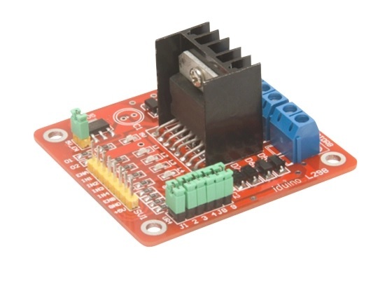
Dual H-Bridge L298N Motor Controller Module for Arduino Projects
Control 2 DC Motors or one Stepper Motor
Using the powerful L298N Dual Motor Driver,this module allows full control of two DC Motors or one stepper-motor. Screw Terminals for easy connections;LEDs show power and output status. Requires six digital inputs. Has 4 mounting holes.
Specification:
- Chip: L298N
- Maximum Output Current:4A
- Storage Temperature: -20 ℃ to +135 ℃
- Operating mode: H-bridge driver (dual)
- Drive voltage: 3-30V DC
- Dimensions: 69x56x36mm
Click here to download instruction manual
The flexible digital input controls allow each motor to be fully independent with complete control over speed direction and braking action.
This board provides a handy 5V regulator that can be used to power other circuitry such as your robots microcontroller. Its modular design is easily adapted to a wide variety of robot controllers including the popular Arduino family.
Features
Popular L298N Dual H-Bridge Motor Driver chip
Drivers motors from 5-35V at up to 2A per channel
Provides 4 LEDs that reflect the state of the control logic
Independent direction, speed and braking for each motor
Screw terminals for easy connections to motors and power
Includes a heavy duty heat sink for maximum performance
Easy to interface with with most robot controllers
Supports current sensing
Handy power LED
Specifications
Input voltage: 5-35V
Output current: 2A per channel
Control logic: standard 5V TTL
Power consumption: 36ma for logic
Size: 55mm * 60mm * 30mm
Weight: 33g
The L298N Dual H-Bridge Motor Driver Board is a great value and can be used with a variety of robot controllers. It features a powerful L298N motor driver module with a heavy duty heat sink. It is powerful enough to drive motors from 5-35V at up to 2A peak.
An onboard 5V regulator is provided that can be used to power other parts of your robot's circuitry such as an Arduino microcontroller.
Usage
Follow the steps below to configure the motor controller board to work as a typical robot motor driver for use with two DC motors.
Attach your robot’s motors to the green Motor A and Motor B screw terminals.
Connect the ENA and ENB to PWM capable digital outputs on your robot’s microcontroller.
Connect the IN1, 2, 3 and 4 pins to any digital outputs your robot’s microcontroller.
Apply 5-16V to the board by connecting positive (+) to the blue VMS screw terminal and ground (-) to the blue GND screw terminal.
See below for details on controlling the motors with your robot’s microcontroller.
All inputs are TTL compatible. Do not enable the onboard 5V regulator if you plan to supply more than 16V to your motors. Refer to the details below.
Hardware Details
Screw terminal pin assignments
Pin Color Name Description
1 Green Motor A - Output to Motor A (-)
2 Green Motor A+ Output to Motor A (+)
3 Blue VMS Input 4-35V motor power supply (+)
4 Blue GND Ground (-)
5 Blue 5V 5V regulated power (+)
6 Green Motor B - Output to Motor B (-)
7 Green Motor B+ Output to Motor B (+)
Note that the 5V regulated power on pin 5 above is an output when the 5V_EN jumper is in place. Otherwise you must input 5V regulated power at pin 5 so that the circuit can operate properly. Do not enable the onboard 5V regulator if you are supplying more than 16V to motors on pin 3 or the regulator will burn out.
Header pin assignments
Pin Name Description
1 ENA Input to enable Motor A
2 IN1 Input to control Motor A
3 IN1 Input to control Motor A
4 ENA Input to enable Motor B
5 IN1 Input to control Motor B
6 IN2 Input to control Motor B
Jumpers
Name Description
5V_EN Enable the onboard 5V regulator
U1 Enable Motor A input pin IN2 pull-up resistor (10K)
U2 Enable Motor A input pin IN2 pull-up resistor (10K)
U3 Enable Motor B input pin IN3 pull-up resistor (10K)
U4 Enable Motor B input pin IN4 pull-up resistor (10K)
CSA Ties the Motor A current sense to ground
CSB Ties the Motor B current sense to ground
Note: The CSA and CSB current sense feature is disabled when the jumpers are present. To use the current sense feature, remove the jumpers and attach to the header pins. Leave the jumper connected when not using current sense.
Software
Speed control
The speed of the motors can be adjusted by connecting PWM outputs from your robot's microcontroller to the ENA and ENB input pins on the motor driver board. The ENA pin controls Motor A and the ENB pin controls Motor B. When these pins are HIGH, power is output to the motor. By using PWM, you are turning power on and off very quickly to adjust the speed of the motor. The longer the PWM duty cycle is, the faster the motor will turn. We recommend always using a PWM duty cycle of 90% or less.
Direction control
The direction that the motors turn is controlled using the IN1, IN2, IN3 and IN4 input pins on the motor driver board. Connect these pins to digital outputs on your robots microcontroller. To make Motor A go forward, set IN1=HIGH and IN2=LOW. To make Motor A go backward set IN1=LOW and IN2=HIGH. The same method is used to control Motor B: set IN3=HIGH and IN4=LOW to o forward and set IN3=LOW and IN4=HIGH to go backwards. Note that "forward" and "backwards" refer to the direction of the motors themselves. If your robot does not move in the expected direction, reverse the motor polarity by swapping the green screw terminals for Motor A + and - and/or Motor B + and -.
Stopping
To remove power from the motors, simply set ENA=LOW for Motor A and ENB=LOW for Motor B. This will result in the motors stopping slowly and naturally from friction. To perform a quick braking operation, set ENA=LOW, IN1=LOW and IN2=LOW for Motor A and ENB=LOW, IN3=LOW and IN4=LOW for Motor B. The motors will come to an instant stop. Here are some handy tables to show the various modes of operation.
Motor Driver Truth Tables
Here are some handy tables to show the various modes of operation.
Motor A truth table
ENA IN1 IN2 Description
0 N/A N/A Motor A is off
1 0 0 Motor A is stopped (brakes)
1 0 1 Motor A is on and turning backwards
1 1 0 Motor A is on and turning forwards
1 1 1 Motor A is stopped (brakes)
Motor B truth table
ENB IN3 IN4 Description
0 N/A N/A Motor B is off
1 0 0 Motor B is stopped (brakes)
1 0 1 Motor B is on and turning backwards
1 1 0 Motor B is on and turning forwards
1 1 1 Motor B is stopped (brakes)
3 Month Warranty
| SKU | TA0052 |
| Barcode # | 9351634002863 |
| Brand | iduino |
| Shipping Weight | 0.0900kg |
| Shipping Width | 0.130m |
| Shipping Height | 0.040m |
| Shipping Length | 0.100m |
| Shipping Cubic | 0.000520000m3 |
| Unit Of Measure | ea |
Dual H-Bridge L298N Motor Drive Module
By: John Carter on 6 November 2022Dual H-Bridge L298N Motor Drive Module performed as expected very happy with the product. Arrived in great condition, although shipping times have been extended of late for many reasons, Aus electronics direct seems to have longer shipping times than other companies, waited longer than expected for this product.
(4)
Great Product
By: Chris Wilson on 30 July 2020As a newbie to this "hobby" I am very happy with the products purchased, value for money and delivery. Now that I am hooked I will definitely need more toys.
(5)
Mrs
By: Amanda Zhu on 31 May 2020Great product , and acceptable price . If the merchant may post some catalog with the item delivery , that will be great for further business opportunities . Tkx Have a good day Amanda
(5)
Stepper Motor Controller Module for Arduino Projec
By: Josef Richmond on 4 July 2019Really consistent product, only bought one initially as I wanted to see how well it suited my purposes. Ended up ordering 2 more as they are work perfectly fine for the cheap price. Delivery is really quick too.
(5)
Great product
By: Josef Richmond on 15 June 2019Have had no problems with it, reliable and easy to use.
(5)
