
13 Example Projects to get you started with Arduino Uno Starter Kit
Author: Aus Electronics Direct Date Posted:22 May 2016
13 Example Projects to get you started with Arduino Uno Starter Kit
Example Projects for Arduino Uno Starter Kit
About the Arduino
The Arduino is an electronics prototyping device. It is essentially a microprocessor with built in serial debugging and USB programming in one device. It has many of the protections and safety features automatically taken care of, including regulating the input power and all of the confusing fuse setting and what not is taken care of by the software, leaving us with an easy to use programming language, and 1 click writing to the board. Arduino essentially allows us to think of a project, and have a prototype up and running extremely quickly. There are modules and “shields” available to expand the abilities of your Arduino. A module is usually a component with its supporting circuitry already added, meaning you can simply plug it in as-is to the Arduino and with a few lines of code, get it working. A “shield” is an expansion for your Arduino that includes circuitry and often a new feature, such as Wi-Fi or Ethernet, USB Host or motor drivers etc. They are generally shaped in such a way that you can plug them in directly to the Arduino board, and they will have headers exposed at the top to then plug your own components into. The board you have may be called an IDUINO or Arduino, or potentially other names also, this is because Arduino are open-source, allowing anyone to use their designs and plans freely. There will be no difference in operation between any of the differently named devices. The model I am using is an IDUINO R3. I also have an Arduino and a duinotech Uno R3, and they are all identical.

About the Breadboard
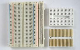
In your starter kit, you received a breadboard. (Pictured right). This breadboard has 2 long horizontal lines along the top and Bottom of it, and then a series of holes throughout the middle. The midsection is connected vertically, with a break in the Middle as shown on the right of the image. The top and bottom Are connected horizontally and are for power distribution. Feel free to google the breadboard for more information!
Before we begin
Before we begin downloading and installing your Arduino, let me begin by talking about the software we will be using. IDE (Integrated Development Environment) is the software we will use to program the Arduino. It translates the code we write into the commands the Arduino expects. It also includes a serial monitor, serial logger and other useful tools and examples. We will be making good use of the Serial Monitor in this guide. Remember, any text you see in the serial monitor was made and sent through the USB cable FROM the Arduino to the computer. This guide is an introduction to the Arduino, it covers most of the components and modules you will find in your starter kit, and includes the code needed to get them all working. You are free to use and modify the code in your own projects, so you have a solid starting point. If you decide to expand your collection of modules later, be sure to shop with Aus Electronics Direct in order to get a guide like this for each additional component!
Installation & setup
First, we must download the latest version of the Arduino IDE. Please navigate to the following URL:
https://www.arduino.cc/en/Main/Software
Follow the steps below to download and install the software and drivers for your Arduino Prototyping Board:
- Run the Arduino installer.
- Install with all the pre-selected options, there is no need to adjust anything here.
- Once the software has installed, plug the USB Cable that came with your kit into the computer, leaving the other end disconnected for the moment.
- Now you can remove your Arduino from the anti-static bag it was shipped in. This small bag can be discarded or kept, it is up to you. The Arduino will not need it any longer, however it will not do it any harm if you decide to store it in there.
- At this point you should have the Arduino IDE installed. There should be a shortcut on your desktop that looks like a blue circle with a white infinity symbol in it. You should also have the Arduino board in front of you and the USB cable plugged in to the computer.
- Plug the USB cable into the Arduino. You should see some lights illuminate on the boards, and your computer may chime to say it has found the board.
- Run the Arduino software, we have 2 settings to verify, then we can dive in to the first project!
- In the Tools menu, please verify that next to Board: is “Arduino / Genuino Uno”. If this is not selected please select this option now.
- And finally, click the Tools menu again, this time clicking PORT: and selecting the port with an associated Arduino as shown below:
Programming Basics
The scariest thing to newcomers is the fact that you have to “program” the Arduino. This sounds much scarier than it really is. That is the beauty of Arduino. There is a team of people involved in making the Arduino as easy to use as possible, they do this by use of an abstraction layer, which takes somewhat easy to read and understand code, and allows it to run on the processor.
.gif)
Code essentials:
Every Arduino sketch (Sketch is the Arduino word for "program") REQUIRES the 2 basic functions:
void setup() {
// put your setup code here, to run once:
}
void loop() {
// put your main code here, to run repeatedly:
}
A few notes about the functions.
- "void" tells the Arduino this function will not return any data, it will simply run when called.
- Functions are cAsE-SENsitIVE. Setup() is not the same as setup() or sEtup().
- The Arduino runs the code in a set order. setup will be run first, once setup() is finished running it will execute loop() repeatedly until you power it down.
- The brackets immediately after the function name are for any data that needs to be passed. setup() and loop() do not make use of this, however we still need to put the empty brackets.
- The curly braces {} tell each function where they start and stop. Always make sure your code falls inside these brackets
- Each function call/command/instruction MUST end in a semicolon ";".
- Finally, "//" tells the compiler to ignore the line, this is useful for writing comments in the code that you can read, but wont affect the program itself.
Project 1 – Serial Output
Expected outcome:
You will learn how to upload code to the Arduino, as well as receive communication back through the USB cable.
What you need:
- Arduino Prototype Board
The Circuit:
In this project we will not be connecting anything to our Arduino, simply executing code and viewing the result.
The Code:
//----Begin Code (copy from here)----
//Variables
void setup() {
// put your setup code here, to run once:
Serial.begin(9600); //Opens the Serial port and sets the data rate
Serial.print("Serial Started..\nHello World!!"); //Prints the string of text to the serial monitor.
//Note - You must enclose strings of text in "" quotes. Otherwise Arduino will think you are talking about a variable.
}
void loop() {
// put your main code here, to run repeatedly:
}
//----End Code (copy to here)----
Try it out:
- Press the “Upload Code” button in the IDE.
- If the Serial Monitor window is not open, open as follows: Tools Menu -> Serial Monitor.
Change the text inside the quotes in the Serial.print(“..”); function call, then re-upload the code. Remember, the Arduino is sending this text to your computer, your computer is only displaying it!
Project 2 – PWM (Pulse-Width Modulation)
Expected outcome:
You will know what PWM is, and see its effects on an LED. You will build your first circuit of the series also!
What you need:
- Arduino Prototype Board
- Breadboard and Jumper Wires
- 1x 1K Resistor (Brown, Black, Black, Brown, Brown)
- Jumper Wires
The Circuit:
Note: The LED will not be damaged if it is placed in backwards, however it will not light until it is swapped to the correct direction.
When you connect the LED, take note there is a “flat” side in the ring around the base, as well as one longer and one shorter leg.
- The flat side, and the shorter lead are to show the Cathode, or the NEGATIVE lead. This goes to the – or the Black wire from the Arduino in the image above.
- The rounder side, with the longer lead is the Anode, or the POSITIVE lead. This goes to +, or in this case, the Arduino pin 6. We will set the pin to put out our Pulse-Width Modulated signal on this pin, and view its effects on the LED.
The Code:
//----Begin Code (copy from here)----
//Variables
int ledPin = 6; //This is a variable. We will discuss this after the code segment!
int pwmVal = 255; //PWM range is 0 - 255. Change this value and reupload to see the difference!
void setup() {
// put your setup code here, to run once:
pinMode(ledPin, OUTPUT); //Set the pin we chose above as OUTPUT.
}
void loop() {
// put your main code here, to run repeatedly:
analogWrite(ledPin, pwmVal); //analogWrite is the arduino function for PWM. We are telling the Arduino to apply a PWM signal to ledPin, with the value of pwmVal which we set at the top of this code.
}
//----End Code (copy to here)----
Variables:
Variables are like containers. You name them, and tell Arduino what type of values or data will be stored...and it keeps track of what’s in there.
In this project we used variables to give names to values we would be using later. This is handy to allow easy changing of values in one place, rather than searching the whole sketch for the values.
Try it out:
Go ahead and click the upload button
Alternate Code:
In addition to the above code, I am including this additional code for you to try. Open the Serial Monitor like we did in the first project and you will be able to watch as the PWM values drop and the LED gets dimmer, and as they rise it gets brighter.
//----Begin Code (copy from here)----
//Variables
int ledPin = 6; //This is a variable. We will discuss this after the code segment!
int pwmVal = 255; //PWM range is 0 - 255. Change this value and reupload to see the difference!
int currVal = 0;
String serialOut = "Current Value: ";
void setup() {
// put your setup code here, to run once:
pinMode(ledPin, OUTPUT); //Set the pin we chose above as OUTPUT.
Serial.begin(9600); //Open serial port
}
void loop() {
// put your main code here, to run repeatedly:
analogWrite(ledPin, pwmVal); //analogWrite is the arduino function for PWM. We are telling the Arduino to apply a PWM signal to ledPin, with the value of pwmVal which we set at the top of this code.
if (pwmVal <= 0) { //If value is 0
pwmVal = 255; //Reset the value to max ready to begin again
}
else { //Otherwise if value is not 0
pwmVal--; //Decrease value by 1
}
Serial.print(serialOut); //Print "Current Value: "
Serial.println(pwmVal); //Add the value to the end of the last line. NOTE this command is println, which adds a newline character at the end of the line. This saves us having to add another "\n".
}
//----End Code (copy to here)----
Feel free to experiment with the code, and when you are ready to move on – lets go from producing light, to detecting it with the next project!
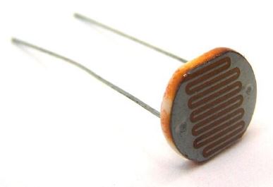
Project 3 – Light Sensor (Photoresistor)
Expected outcome:
You will know how to interface with, and use an LDR with your Arduino. This code will help you in your own projects if you need to use an LDR in the future.
What you need:
- Arduino Prototype Board
- Breadboard and Jumper Wires
- 1x 220Ohm Resistor (Red, Red, Brown, Gold)
- 1x LDR/Photoresistor (Pictured to the right)
The Circuit:
The Code:
//----Begin Code (copy from here)----
//Variables
int inPin = A0; //Pin the sensor is connected to
int sensorVal = 0; //Variable to store sensor data
void setup() {
// put your setup code here, to run once:
Serial.begin(9600);
Serial.println("Serial Communication started...\n");
}
void loop() {
// put your main code here, to run repeatedly:
sensorVal = analogRead(inPin); //analogRead will read the voltage on the pin specified and return it as a value between 0 and 1024.
Serial.println(sensorVal); //Print the sensor reading to the serial window so we can view the data.
}
//----End Code (copy to here)----
Try it out:
You should see numbers in the Serial Monitor window that increase as more light hits the sensor, and decrease as less light hits it. If you cover it completely you will see a 0;
What is your baseline? Consider the average reading when you allow the natural light of the room to hit the sensor. How large is the variance? If the minimum number was 10 and the maximum was 15, you would have a variance of 5 and an average baseline of 12. This sort of information is useful when designing code to do certain things...establish levels and have things happen when sensor readings drop below or rise above certain levels...In this case you could make a night light, that turns on when the room darkens, and off again when it is bright enough!
Have a play with the circuit...What types of light affect the sensor? Flame (Don't burn the sensor)? Phone screen? Torch? Sunlight? Glow stick?
What do you think this could be used for?
Congratulations on your first sensor input!
Let’s move on to the next project now that you can read analog sensors, this time we are going to be looking at a FLAME DETECTOR.
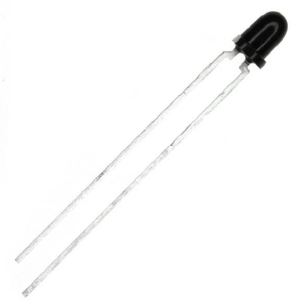
Project 4 – Flame Sensor
Expected outcome:
You will interface a flame sensor to the Arduino. This sensor is specially designed to isolate specific bands in the IR and UV wavelengths and looks for unique patterns in flames for an extremely accurate reading.
What you need:
- Arduino Prototype Board
- Breadboard and Jumper Wires
- 1x Flame Sensor (Pictured Right)
- 1x 220 Ohm Resistor. (Brn, Blk, Blk, Red, Red)
The Circuit:
Note: If you get no reading when igniting a flame near the sensor, try reversing it. It is a polar device and needs to be in the correct way. It will not be damaged in this circuit if it is placed backwards.
The Code:
//----Begin Code (copy from here)----
//Variables
int inPin = A0; //Pin the sensor is connected to
int sensorVal = 0; //Variable to store sensor data
void setup() {
// put your setup code here, to run once:
Serial.begin(9600);
Serial.println("Serial Communication started...\nReady to detect Flame.");
}
void loop() {
// put your main code here, to run repeatedly:
sensorVal = analogRead(inPin); //analogRead will read the voltage on the pin specified and return it as a value between 0 and 1024.
if (sensorVal < 1000) {
//Flame
Serial.print("Flame: ");
Serial.println(sensorVal);
}
else {
//Uncomment the lines below to view the raw sensor data.
//You can change the "if statement" above to reflect the difference in sensitivity and ambient values
//Serial.print("Sensor Value: ");
//Serial.println(sensorVal);
}
}
//----End Code (copy to here)----
Try it out:
Upload and run the code. You should see the Serial monitor display:
Serial Communication started...
Ready to detect Flame.
If you now light a lighter within the detection radius of the sensor, you will see the serial monitor output:
Flame: xxx
Where xxx is the sensor reading.
Now that we can detect a flame, we can move along to the next project! Capturing and using data from an IR remote control!
Project 5 – Remote
Expected outcome:
You will build a circuit to demodulate and report the codes of individual buttons of various IR remotes around the house, as well as the one in the kit. If you wish to build a project based off this circuit you should google “Arduino switch” and select the link with the title “switch case”. This will show you the method for executing different actions depending on the remote code received.
What you need:
- Arduino Prototype Board
- Breadboard and Jumper Wires
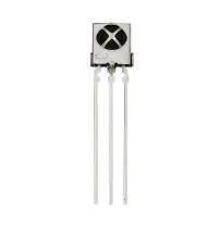
- 1x IR Receiver and Remote (Receiver pictured right)
- IRremote library from: https://www.pjrc.com/teensy/arduino_libraries/IRremote.zip
NOTE: In this project we are using a library for the first time. The library will download as a ZIP file. You should then extract the files to your Arduino installation folder/libraries
eg: C:\Program Files (x86)\Arduino\libraries
If you have problems with this step google search “Using libraries with Arduino” for easy to follow guides.
The Circuit:
Note: The sensor should face you, so when you click a button on the remote it can easily pick it up.
The Code:
//----Begin Code (copy from here)----
#include <IRremote.h> //Notice we have included the IRremote library here.
//Variables:
IRrecv irrecv(10); //Set up the IR Reciever, call it irrecv and attach it to the correct pin
decode_results results; //Set up a variable to hold the results
void setup()
{
// put your setup code here, to run once:
Serial.begin(9600);
irrecv.enableIRIn(); // Start the receiver
irrecv.blink13(true); //Blinks the LED on the Arduino board as it gets data from the remote.
}
void loop() {
// put your main code here, to run repeatedly:
if (irrecv.decode(&results)) {
String tmp = (String)results.value;
if (tmp == "4294967295") //This value tells the Arduino that the previous button is still active.
{
Serial.println("Button still active."); //Report to the serial monitor the last button was still held down
}
else {
Serial.println(results.value, HEX); //A new button has been pressed with the value shown.
}
irrecv.resume(); // Receive the next value
}
}
//----End Code (copy to here)----
Try it out:
Upload the code and open the serial monitor.
Aim the included remote at the receiver (the side with the metal X crossing it) and watch the serial output window! What projects would you make using this method of remote control?
It wouldn’t take much code to start looking for specific hex codes, and performing tasks based on which input was observed! Our future project books will cover some fun topics using the remote!
Feel free to have a play with various IR transmitters from around your house...When you are ready, let’s move on to the next project – Tilt Sensors!
Project 6 – Tilt Sensor
Expected outcome:
You will learn to interface with the simple tilt sensor. This sensor is essentially a steel bearing in a tube. The leads go inside, and when the bearing is at the bottom of the can it completes the circuit. When the bearing rolls up the can the circuit is broken.
What you need:
- Arduino Prototype Board
- Breadboard and Jumper Wires
The Circuit:
Note: This component has no polarity, it can be inserted either way and work the same. The leads are often bent various ways in order to have it activate and deactivate at the correct angles.
The Code:
//----Begin Code (copy from here)----
//Variables:
void setup() {
// put your setup code here, to run once:
Serial.begin(9600);
Serial.println("Serial Established..\nTilt board to continue.");
pinMode (7, INPUT); //Set pin 7 to input for reading the sensor.
}
void loop() {
// put your main code here, to run repeatedly:
if (digitalRead(7) == true)
{
Serial.println("Tilted!");
}
else {
Serial.println("Upright!");
}
}
//----End Code (copy to here)----
Try it out:
Notice that if you tilt the board the output changes from upright to tilted. You could use this sensor to start a function that makes your robot stand up for instance.
Now that we have added another sensor to the list of components we can use, let’s move forward to another type of output! The RGB LED module!
Project 7 – RGB LED Control
Expected outcome:
You will be able to control the color output of an RGB LED module from your Arduino.
What you need:
- Arduino Prototype Board
- Breadboard and Jumper Wires
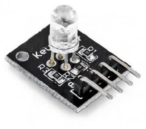
- 1x RGB Module (Pictured Right)
The Circuit:
Note: the image is slightly different to the module you got, however it is wired the same. The LED should be towards you. It will be quite bright. I recommend a piece of paper or tissue over the lens.
The Code:
//----Begin Code (copy from here)----
//Variables:
int rPin = 11;
int gPin = 10;
int bPin = 9; //Set the PWM pins to be used on the arduino
int rVal = 0;
int gVal = 0;
int bVal = 0; //Set the values to 0 to begin with
void setup() {
// put your setup code here, to run once:
//No setup for this project.
}
void loop() {
// put your main code here, to run repeatedly:
analogWrite(rPin, rVal);
analogWrite(bPin, bVal);
analogWrite(gPin, gVal); //Apply PWM output to each leg of the RGB LED, with the value stored in the corresponding variable.
rVal = random(0,255);
gVal = random(0,255);
bVal = random(0,255); //Randomise the variables to get a random color each time
delay(500); //Delay before changing colors, so we can see each change.
}
//----End Code (copy to here)----
Try it out:
The RGB LED should now cycle through random colors, every half a second the color should change. The LED is quite bright, I found it much easier to look at once I had placed a small piece of printer paper over the top of it, it also helps mix the colors better.
If you wish to experiment with mixing your own colors, delete the following section of code:
rVal = random(0,255);
gVal = random(0,255);
bVal = random(0,255); //Randomise the variables to get a random color each time
delay(500); //Delay before changing colors, so we can see each change.
And now you can set the values for each color in the Variables section. When you compile and run you will see your custom color there!
Now that we can use an RGB LED in our projects, let’s move on to reading a potentiometer.
Project 8 – Read a potentiometer
Expected outcome:
You will be able to take user input and process it. You might use this as an input for sensitivity, volume, intensity, or even as an analog input for a game controller or similar.
What you need:
- Arduino Prototype Board
- Breadboard and Jumper Wires
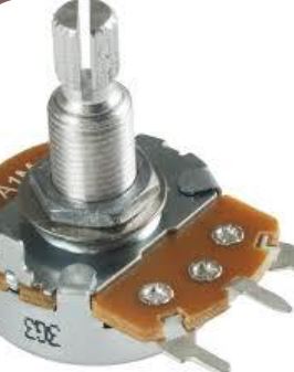
- 1x Potentiometer (Pictured right)
- 1x 220 Ohm Resistor. (Brn, Blk, Blk, Red, Red)
The Circuit:
Note: Ensure the control stick is towards you so you can spin it easily.
The Code:
//----Begin Code (copy from here)----
//Variables:
int varPin = A0;
int val = 0;
void setup() {
// put your setup code here, to run once:
Serial.begin(9600);
Serial.println("Serial connection established..\nAdjust the Potentiometer to see the value change!");
}
void loop() {
// put your main code here, to run repeatedly:
Serial.print("Potentiometer Value: ");
val = analogRead(varPin);
Serial.println(val);
}
//----End Code (copy to here)----
Try it out:
Notice how the number reading in the Serial Monitor changes depending on the position of the potentiometer. What projects could you make with this?
Let’s move on to the next component! A 7-Segment display!
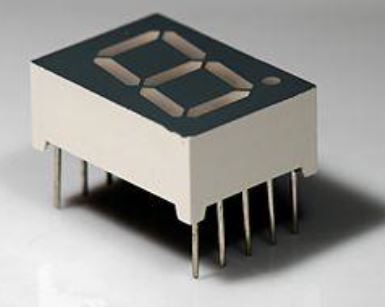
Project 8 – 7 Segment Display
Expected outcome:
You will wire up and display all the HEXADECIMAL characters on the 7-Segment. Notice there is no possible way to reliably make all the characters using this display, however they are great for numbers. You can also somewhat fashion a workable alphabet if you use a combination of upper and lowercase letters, and they don’t have to be exactly right.
What you need:
- Arduino Prototype Board
- Breadboard and Jumper Wires
- 1x 7-Segment Display module
The Circuit:
The Code:
//----Begin Code (copy from here)----
//Variables:
int pin_a = 6;
int pin_b = 7;
int pin_c = 8;
int pin_d = 9;
int pin_e = 10;
int pin_f = 11;
int pin_g = 12;
int pin_h = 13;
int delayVar = 500;
void setup() {
// put your setup code here, to run once:
pinMode(pin_a, OUTPUT);
pinMode(pin_b, OUTPUT);
pinMode(pin_c, OUTPUT);
pinMode(pin_d, OUTPUT);
pinMode(pin_e, OUTPUT);
pinMode(pin_f, OUTPUT);
pinMode(pin_g, OUTPUT);
pinMode(pin_h, OUTPUT);
}
void loop() {
// put your main code here, to run repeatedly:
ch_0();
delay(delayVar);
ch_1();
delay(delayVar);
ch_2();
delay(delayVar);
ch_3();
delay(delayVar);
ch_4();
delay(delayVar);
ch_5();
delay(delayVar);
ch_6();
delay(delayVar);
ch_7();
delay(delayVar);
ch_8();
delay(delayVar);
ch_9();
delay(delayVar);
ch_a();
delay(delayVar);
ch_b();
delay(delayVar);
ch_c();
delay(delayVar);
ch_d();
delay(delayVar);
ch_e();
delay(delayVar);
ch_f();
delay(delayVar);
delay(delayVar);
}
void ch_a()
{
digitalWrite(pin_a, LOW);
digitalWrite(pin_b, HIGH);
digitalWrite(pin_c, LOW);
digitalWrite(pin_d, HIGH);
digitalWrite(pin_e, HIGH);
digitalWrite(pin_f, HIGH);
digitalWrite(pin_g, HIGH);
digitalWrite(pin_h, HIGH);
}
void ch_b()
{
digitalWrite(pin_a, LOW);
digitalWrite(pin_b, HIGH);
digitalWrite(pin_c, HIGH);
digitalWrite(pin_d, HIGH);
digitalWrite(pin_e, HIGH);
digitalWrite(pin_f, HIGH);
digitalWrite(pin_g, HIGH);
digitalWrite(pin_h, HIGH);
}
void ch_c()
{
digitalWrite(pin_a, LOW);
digitalWrite(pin_b, LOW);
digitalWrite(pin_c, HIGH);
digitalWrite(pin_d, HIGH);
digitalWrite(pin_e, LOW);
digitalWrite(pin_f, HIGH);
digitalWrite(pin_g, HIGH);
digitalWrite(pin_h, LOW);
}
void ch_d()
{
digitalWrite(pin_a, LOW);
digitalWrite(pin_b, HIGH);
digitalWrite(pin_c, HIGH);
digitalWrite(pin_d, HIGH);
digitalWrite(pin_e, HIGH);
digitalWrite(pin_f, LOW);
digitalWrite(pin_g, LOW);
digitalWrite(pin_h, HIGH);
}
void ch_e()
{
digitalWrite(pin_a, LOW);
digitalWrite(pin_b, LOW);
digitalWrite(pin_c, HIGH);
digitalWrite(pin_d, HIGH);
digitalWrite(pin_e, LOW);
digitalWrite(pin_f, HIGH);
digitalWrite(pin_g, HIGH);
digitalWrite(pin_h, HIGH);
}
void ch_f()
{
digitalWrite(pin_a, LOW);
digitalWrite(pin_b, LOW);
digitalWrite(pin_c, LOW);
digitalWrite(pin_d, HIGH);
digitalWrite(pin_e, LOW);
digitalWrite(pin_f, HIGH);
digitalWrite(pin_g, HIGH);
digitalWrite(pin_h, HIGH);
}
void ch_1()
{
digitalWrite(pin_a, LOW);
digitalWrite(pin_b, HIGH);
digitalWrite(pin_c, LOW);
digitalWrite(pin_d, LOW);
digitalWrite(pin_e, HIGH);
digitalWrite(pin_f, LOW);
digitalWrite(pin_g, LOW);
digitalWrite(pin_h, LOW);
}
void ch_2()
{
digitalWrite(pin_a, LOW);
digitalWrite(pin_b, LOW);
digitalWrite(pin_c, HIGH);
digitalWrite(pin_d, HIGH);
digitalWrite(pin_e, HIGH);
digitalWrite(pin_f, HIGH);
digitalWrite(pin_g, LOW);
Title 26
Date
digitalWrite(pin_h, HIGH);
}
void ch_3()
{
digitalWrite(pin_a, LOW);
digitalWrite(pin_b, HIGH);
digitalWrite(pin_c, HIGH);
digitalWrite(pin_d, LOW);
digitalWrite(pin_e, HIGH);
digitalWrite(pin_f, HIGH);
digitalWrite(pin_g, LOW);
digitalWrite(pin_h, HIGH);
}
void ch_4()
{
digitalWrite(pin_a, LOW);
digitalWrite(pin_b, HIGH);
digitalWrite(pin_c, LOW);
digitalWrite(pin_d, LOW);
digitalWrite(pin_e, HIGH);
digitalWrite(pin_f, LOW);
digitalWrite(pin_g, HIGH);
digitalWrite(pin_h, HIGH);
}
void ch_5()
{
digitalWrite(pin_a, LOW);
digitalWrite(pin_b, HIGH);
digitalWrite(pin_c, HIGH);
digitalWrite(pin_d, LOW);
digitalWrite(pin_e, LOW);
digitalWrite(pin_f, HIGH);
digitalWrite(pin_g, HIGH);
digitalWrite(pin_h, HIGH);
}
void ch_6()
{
digitalWrite(pin_a, LOW);
digitalWrite(pin_b, HIGH);
digitalWrite(pin_c, HIGH);
digitalWrite(pin_d, HIGH);
digitalWrite(pin_e, LOW);
digitalWrite(pin_f, HIGH);
digitalWrite(pin_g, HIGH);
digitalWrite(pin_h, HIGH);
}
void ch_7()
{
digitalWrite(pin_a, LOW);
Title 27
Date
digitalWrite(pin_b, HIGH);
digitalWrite(pin_c, LOW);
digitalWrite(pin_d, LOW);
digitalWrite(pin_e, HIGH);
digitalWrite(pin_f, HIGH);
digitalWrite(pin_g, LOW);
digitalWrite(pin_h, LOW);
}
void ch_8()
{
digitalWrite(pin_a, LOW);
digitalWrite(pin_b, HIGH);
digitalWrite(pin_c, HIGH);
digitalWrite(pin_d, HIGH);
digitalWrite(pin_e, HIGH);
digitalWrite(pin_f, HIGH);
digitalWrite(pin_g, HIGH);
digitalWrite(pin_h, HIGH);
}
void ch_9()
{
digitalWrite(pin_a, LOW);
digitalWrite(pin_b, HIGH);
digitalWrite(pin_c, HIGH);
digitalWrite(pin_d, LOW);
digitalWrite(pin_e, HIGH);
digitalWrite(pin_f, HIGH);
digitalWrite(pin_g, HIGH);
digitalWrite(pin_h, HIGH);
}
void ch_0()
{
digitalWrite(pin_a, LOW);
digitalWrite(pin_b, HIGH);
digitalWrite(pin_c, HIGH);
digitalWrite(pin_d, HIGH);
digitalWrite(pin_e, HIGH);
digitalWrite(pin_f, HIGH);
digitalWrite(pin_g, HIGH);
digitalWrite(pin_h, LOW);
}
//----End Code (copy to here)----
Try it out:
What we have done here is create a function for each character that we will display. In this case I have included the full HEX range. Perhaps you can merge this and the IR remote project, to have this display read off the code captured from the remotes.
You could of course create more functions for the rest of the alphabet. In my next project book I will rewrite this code so instead of specifying a function for each character, we will instead call a function with the string we want to display as a parameter like so:
displayString("String");
The displayString function will then work out the individual characters in the string and light them in order on the display with a configurable delay. It will also support the full stop which Right now I have not added.
To add more characters try setting all the pins to LOW except one (making sure to call the function you are modifying in the loop()). This will illuminate one section of the display. Once you have done this for each section and written down which pin corresponds to which segment you can create any shape possible as I have done :).
Let’s move on to the next module, the Passive Buzzer!
Project 10 – Passive Buzzer
Expected outcome:
You will be able to use a passive buzzer, which is essentially a small speaker. You cannot just apply 5V to this as it will only move the cone in one direction. We can however use the PWM function to drive the coil both ways and emit steady tones. The example code below will play random pitched sounds through the speaker.
What you need:
- Arduino Prototype Board
- Breadboard and Jumper Wires
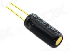
- 1x Passive Buzzer module (Mine has a visible circuit board underneath whereas the active buzzer does not.)
The Circuit:
The Code:
//----Begin Code (copy from here)----
//Variables:
void setup() {
// put your setup code here, to run once:
pinMode(6, OUTPUT);
Title 30
Date
}
void loop() {
// put your main code here, to run repeatedly:
//digitalWrite(6, HIGH);
analogWrite(6, random(0,255));
delay(500);
}
//----End Code (copy to here)----
Try it out:
Once you run the code you should hear random sounds at random pitches. You could use this module to play a fixed pitch sound to signify button presses, errors or similar status feedback. In concert with an RGB LED this is all the notification you would need.
Let’s move on to the Active Buzzer next!
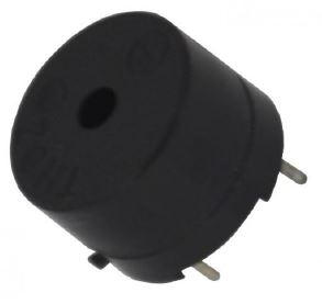
Project 10 – Active Buzzer
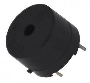
Expected outcome:
You will be able to use an active buzzer, it differs from the passive buzzer in the last project as all we have to do it provide a 5V connection to it to produce sound, it has its own circuit inside to drive the speaker. We can still supply PWM to modulate the pitch, although it is not necessary in this case.
What you need:
- Arduino Prototype Board
- Breadboard and Jumper Wires
- 1x Active Buzzer module (Mine has a black resin seal underneath whereas the passive buzzer does not.)
The Circuit:
The Code:
//----Begin Code (copy from here)----
//Variables:
void setup() {
// put your setup code here, to run once:
pinMode(6, OUTPUT);
}
Title 32
Date
void loop() {
// put your main code here, to run repeatedly:
digitalWrite(6, HIGH);
delay(500);
digitalWrite(6, LOW);
delay(500);
}
//----End Code (copy to here)----
Try it out:
Notice the buzzer creates a clear sound by simply applying power to it. If we used this same sketch on the passive speaker we would hear a very tiny blip and then nothing at all.
Let’s move on the next project: Buttons (and debouncing them)
Project 12 – Buttons
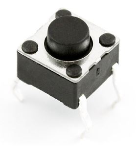
Expected outcome:
You will be able to interface buttons with your Arduino. This is actually not as simple as it sounds, we need to employ some clever code to “debounce” the button signal, or we will get a series of presses rather than one clean press signal.
What you need:
- Arduino Prototype Board
- Breadboard and Jumper Wires
- 1x Micro Tactile Button (Pictured right)
- 1x 220 Ohm Resistor. (Brn, Blk, Blk, Red, Red)
The Circuit:
The Code:
//----Begin Code (copy from here)----
//Variables:
int buttonPin = 7; //Pin button is connected to
int buttonState; //Variable to store button state
int lastButtonState = LOW; //Variable to store last state
long lastDebounceTime = 0; //Variable to store time button was last pressed
Title 34
Date
long debounceDelay = 50; //Minimum amount of time in milliseconds to wait between presses. (1000 milliseconds per second)
void setup() {
// put your setup code here, to run once:
Serial.begin(9600);
pinMode(buttonPin, INPUT);
Serial.println("Serial communication established...\nPress Button to test.");
}
void loop() {
// put your main code here, to run repeatedly:
int reading = digitalRead(buttonPin);
if (reading != lastButtonState) {
lastDebounceTime = millis();
}
if ((millis() - lastDebounceTime) > debounceDelay) {
if (reading != buttonState) {
buttonState = reading;
if (buttonState == HIGH) {
//Button pressed
buttonPressed();
}
}
}
lastButtonState = reading;
}
void buttonPressed()
{
Serial.println("Press!");
}
//----End Code (copy to here)----
Try it out:
Notice how the button is crisp and doesn’t give any false presses.
That is it for the beginner series of projects! We hope this series has given you practical examples and uses for your Arduino and components! Our future project books will focus on creating full projects, games, tools, sensors and the like. This series was designed to introduce you to your kit and show you how to use each component.
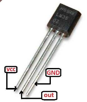
Project 13 – LM35 Temperature Sensor
Expected outcome:
You will be able to read temperatures with an LM35 analog temperature sensor! This is a great final project, a digital thermometer!
What you need:
- Arduino Prototype Board
- Breadboard and Jumper Wires
- 1x LM35 Temperature Sensor(Pictured right)
The Circuit:
Note: Make sure the flat side is facing you, as seen in the image, and all connections are as shown. This component is polar and will heat up and degrade in sensitivity the longer it is left connected backwards.
The Code:
//----Begin Code (copy from here)----
//Variables:
int varPin = A0; //A0 is the analog in pin
int val = 0; //This will store the current value from the sensor
int oldVal = 0; //This will store the last value from the sensor to compare.
void setup() {
// put your setup code here, to run once:
Serial.begin(9600);
Serial.println("Serial connection established..\nTemperature logging started!");
}
void loop() {
// put your main code here, to run repeatedly:
oldVal = val; //Store the last value in the variable
val = analogRead(varPin); //Store the new value in its variable
if (oldVal != val) //If the temperature has changed, tell us the new temp
{
Serial.print("Temp: ");
Serial.print(5.0 * val * 100 / 1024); //please see note at bottom regarding this formula.
Serial.println(" Degrees(Celsius)");
}
delay(500); //Wait half a second, then do it again. (This allows the line to settle between reads. Not really required, but it does remove a bit of jitter
}
//----End Code (copy to here)----
Try it out:
The formula used to convert to temperature was derived from the data sheet. In this case we have the following elements:
5.0 is the voltage we are inputting.
100 is the multiplier to convert from mV to V
1024 is the maximum resolution of the analog input on the arduino.
Essentially we know from the data sheet that 10mV = 1 degree, which means if we convert and clean the reading using the above formula, we get the temperature in Degrees Celsius -/+ half a degree.
You will notice the temperature will display in the serial monitor. If you touch the sensor you will see the reading go up, and once you let go you will see it drop back down as the sensor cools.
Using the knowledge I have imparted upon you, do you think you can combine any of the projects we have performed in order to make something new?
You could use an RGB LED to change colors depending on the temperature range...
Perhaps a buzzer could alert you if the temperature goes over a certain reading...(Home brew beer for instance)
The Arduino makes it really easy to build anything you can think of. Don't forget to check out the code references on the Arduino website, as well as google anything at all you need help with.
If you would like to contact the author, you can do so via prot3us1@gmail.com.

