
Installation Guide for Dual Mains Outlet with 2x 2A USB
Author: Aus Electronics Direct Date Posted:1 May 2016
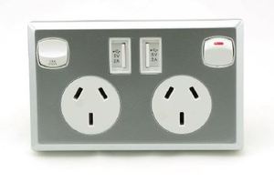
Installation Guide for Dual Mains GPO Power Outlet with 2x 2A USB
FOR LICENSED ELECTRICIANS ONLY - NOT FOR USER INSTALLATION - MAINS VOLTAGES ARE FATAL
About this guide
This guide is intended for licensed electricians only. This device operates on mains voltage, which in Australia is 240V – Enough to be fatal.
In the process of installing this device, personnel WILL come into contact with wiring that can carry lethal voltages and current. If you are not suitably qualified to perform this installation, please call an electrician who is.
Safety
As with all projects involving mains electricity we have to be extremely careful. Double and triple checking as well as using the correct tools and equipment. One moment is all it takes for a fatal mistake.
You will need at minimum:
- Power outlet
- Multimeter
- Insulated Screwdriver
- Insulation Strippers
- Pliers
- Side Cutters
About the product:
Click Here to see a list of these products available at Aus Electronics DIrect
NOTE: The following is my own opinion, and not necessarily shared by the manufacturer, or supplier.
This is a great product. I monitored the USB output over 5 days, with varying loads and the results are very promising. The output is stable and nothing caught fire when I shorted it out for 30 seconds. I am not advocating purposefully messing with this socket, however I am certainly impressed with this product.
The USB sockets I would describe as feeling “silky”. You will understand when you try one…the plug slides in, it doesn’t take too much force, and they certainly don’t feel like they would just fall out either.
Step 1: Turn off switchboard
(Licensed electricians ONLY)
Turn off all fuses and supply switches in the main breaker box. This isolates the internal wiring on the premises from the grid, and will allow us to work on the cabling without fear of electrocution or shorting. Please make sure everyone is aware you are working on the wiring, and knows not to switch the power back on until you do it yourself.
* Always use lockout tags when available.
Step 2: Check the outlet for voltage
(Licensed electricians ONLY)
Once you have isolated the outlet through the switchboard you should double check the outlet with your multimeter. With the meter in the correct range (hundreds V AC) insert the probes into the top slanted female holes and observe the meter. It should read 0V. Now toggle the switch. The meter should still read 0V.
If any voltage is found DO NOT PROCEED. Call a licensed electrician. At this point all you have to do is turn the switchboard back on. You WILL be injured if you work on a live outlet. DO NOT DO IT.
Step 3: Remove the old wall plate
(Licensed electricians ONLY)
Once you have a safe (dead) socket you can proceed. The vast majority of sockets will have 2 screws to remove. About midway down the outlet, and on the left and right edges. Sometimes they are concealed by caps, you should see 2 round protrusions if that is the case. Remove the caps and screws. The old outlet will now be free of the wall.
At this point I like to check for voltage again, where the wires enter the receptacles. If I get a 0V reading again here I will be confident with proceeding.
With a second safety check complete, I locate the screws that are holding the wires into their receptacles. There are multiple designs for this, they are fairly easy to locate as they are often directly in contact with the wires themselves. Loosen these screws and the wiring will come out easily.
Step 4: Preparation
(Licensed electricians ONLY)
Some older houses have smaller mounting hardware on their sockets, and this may interfere with installation. If you can fit the new socket into the hole until it is flush with the wall, you are fine. If not you will need to purchase a new mounting bracket from your local hardware store. These are extremely cheap, and you simply remove the old one and fit the new one. In my case the old one was held in with 2 nails on one side only, and I was able to simply pull it out with pliers. I fit the new one with screws to make it easier, seeing as I could not swing a hammer in the hole. I used the old nail holes as the pilot holes for the screws.
There is only 1 circuit needed to be connected to this outlet. If you have 2 sets of wires (ie: 2x blue, 2x brown and 2x green) then you will want to combine them to form a single set.
DO NOT LEAVE A SET HANGING UNTERMINATED. THIS WILL CAUSE A FIRE.
Take the 2 blue wires, and twist them together to form a tight spiral about 1cm long.
Do the same for the Green/Yellow and brown wires.
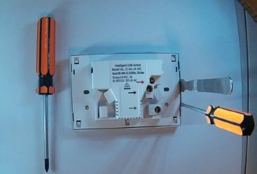
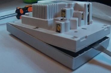
Finally, remove the faceplate by gently inserting a prier or flathead screwdriver as shown, and gently separating the 2 parts.
Step 5: Installation
(Licensed electricians ONLY)
At this point you will have effectively 3 wires in front of you. This may be 3 single wires, or 6 wires combined to form 3 sets of 2. Either way, we will have a green/yellow wire, a blue wire and a brown wire. There are some cases when the colors will be different, such as really old houses etc. The conversion is below:
Australia:
- Green / yellow = earth
- Black / blue = neutral
- Red / brown = active
We will now trim the exposed inner wire from 1cm down to between 50 and 80mm. This is important. A good termination should not leave any of the inner wire exposed. Don’t rush this, it is a huge fire risk.
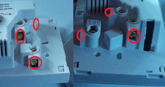
On the back of the plug you will notice there are 3 arrows pointing to the 3 receptacles for the mains input. Red, Black and Green. You may notice also, that we have those colors listed above. We simply need to plug the appropriate wire into the correct screw-terminal, and we are done! The USB ports are powered automatically internally.
Take the brown wire(s) and insert them into the top hole, with the RED arrow. This is the active wire. With the wire inserted firmly, tighten the screw associated with that terminal. You want it very firm, but you don’t want to create a weak point in the wire that will break. It should be tightened so the wire will not come out and left at that point. If you tug the wire it should not move at all.
Next repeat the process for the blue wire(s), into the BLACK arrow receptacle.
Finally you will complete the wiring step by repeating the process a final time with the green/yellow wire(s).
Step 6: Mounting in the wall
(Licensed electricians ONLY)
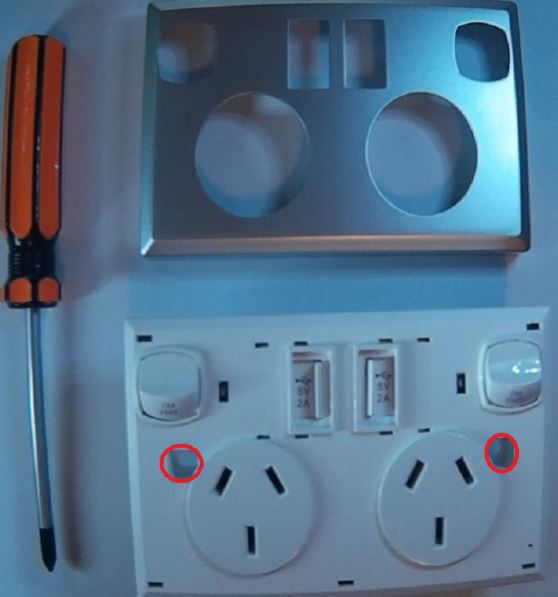
In order to fix the plate to the wall securely you will need to place the screws through the holes marked in the following image, these screws should then be inserted into the mounting bracket located inside the wall from the Preparation step. Replace the front cover after this step and you have completed installation!
Having safely installed the hardware, you can now turn the household supply back on at the switchboard. Feel free to test the outputs with your meter to ensure 240V is present (or plug a lamp in).
The USB ports have handy dust covers which are gently spring loaded, simply slide this across and insert the USB plug into the socket. The cover will re-engage itself automatically when you remove the plug.
Enjoy having the convenience of a 2Amp USB port right there at the socket!