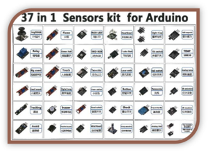
Building with the 37 in 1 Sensor Kit for Arduino Module
Author: Aus Electronics Direct Date Posted:14 May 2016
Building with the 37 in 1 Sensor Kit for Arduino Module
Foreword
This guide is a brief rundown of the sensors you will find in this kit. The kit is more of a starter set for Arduino, there are 37 components inside, however there are not 37 individual sensors.
There are also LEDs, and other modules in the kit. That would perhaps be a better name for the kit. 37 – in – 1 module kit.
Regardless, you have purchased a fantastic set of components to get you started! You can measure light, time, magnetic fields, temperature, humidity…you can measure sound and create sound, you can measure tilt and user input! All of these components are presented on easy to access boards and allow you to connect them rapidly to the Arduino board.
Key Skill – Installing Libraries
What is a library?
A library is a repository of functions. It is a set of files that contain code that can run your modules, usually with a really simple way of interfacing and controlling your project. For instance, we can include a library to control an OLED display…We will then not have to worry about coding any of the difficult and time consuming Arduino->screen communication protocol, instead we can simply draw on the screen. It is in a small way like drivers on your computer, although libraries might include math functions, graphics functions, there is a library called bounce that debounces inputs! I will show you how to find and install these libraries in this guide.
How do I find these libraries in order to install them?
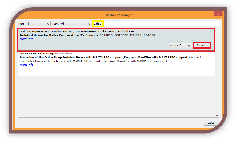
Arduino IDE includes a nice little interface called the library manager where we can search and install libraries without needing to copy any files etc, it is all done automatically! In the Arduino IDE locate the menu bar at the top of the window. (File..Edit..Sketch)
To open Library Manager: Click the Sketch menu->Include Libraries->Manage Libraries
This will open the Library Manager window. Here you can search for libraries, select the one you like and click install. The library will then be installed.
How do I access the library, once it is installed?
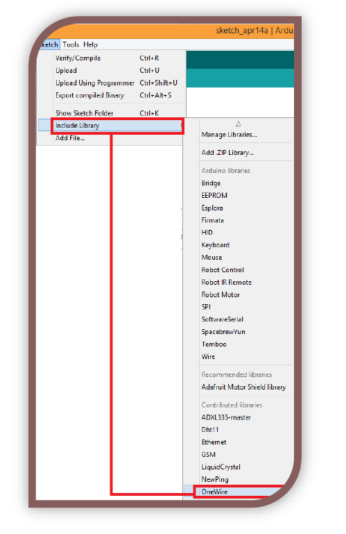
Once the library manager installs the library a confirmation message will appear above the black output window at the base of the IDE. You can then locate the libraries you have installed through the Sketch menu as follows:
Open the Sketch menu->Include Library->Select the library you wish to include. This will add the #Include statement automatically at the top of the sketch.
You can also install libraries by allowing the library manager to unzip them and add the files to the correct directory, or manually adding the files to the directory…If you come across those scenarios however, there will be instructions included on the page along with them.
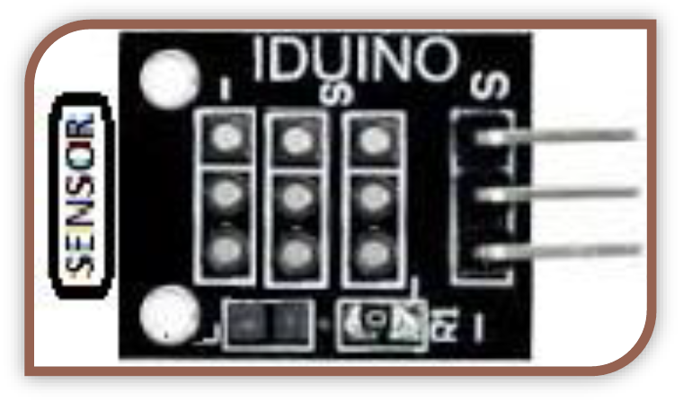
MODULES – The 3-pin Analog Sensor Module
Voltage (Min-Max): 3-5V
# of Pins used: 3
Type of pins used: ANALOG
Which Sensors does this apply to?
This applies to any sensor that has 3 pins and puts out a voltage proportionate to its value.
In the 37-in-1 kit this includes:
- Photoresistor Measures light, resistance varies depending on brightness
- Analog Hall Measures movement through magnetic fields
- Hall Magnetic (Yes, similar device to analog hall) Measures movement through magnetic fields. This one has an LED that lights in the presence of a strong field.
Why are a lot of sensors so similar to use?
In electronics voltage is fairly easy to determine, as well as being easy enough to manipulate and retain its value. The vast majority of sensors will fit this description, sometimes they are mounted on boards that might add features, such as the “Analog/Digital Sensor module” boards.
- The sensor will have an input voltage, and ground connection and a pin that will output a value that is between the input and 0V. The value will be directly proportionate to the measurement made.
- The pins will be labeled, and may not always be in the same order, so hook them up the way they are labelled even if it is slightly different to this guide. This guide is accurate for any sensor mounted on the board pictured on the section-intro above.
By making these modular boards able to take any sensor essentially and have hobbyists simply able to use it, regardless of having read the fact-sheet etc is amazing! Arduino is simply an amazing system.
The pins on these modules are as follow:
- S: Signal/Sensor Out
- This pin will output a voltage between 0v and + which is directly proportionate to the measurement of the sensor. This pin is connected to an analog in.
- +: Vs/ Positive supply (5V max)
- The middle pin is for +5V or +3.3V. This will power the sensor and give a reference voltage for the output. This will be connected to +5V or +3.3V on the Arduino.
- -: GND
- The final leg is GND and allows a return path for current, completing the circuit. This should be connected to your Arduino GND.
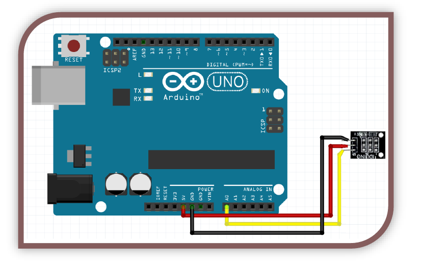
Example Circuit:
In this configuration we use “analogRead(A0)” to get the analog value.
Example Code:
//----Begin Code (copy from here)----
/*
Set the variables below to the desired values, there are also predefined
functions at the bottom of the sketch you can use in your own projects
*/
//Includes:
//Variables:
int delayVal = 500; //Time to delay between reads.
int debug_values = 1; //1 = show values in serial / 0 = hide.
void setup() {
// put your setup code here, to run once:
Serial.begin(9600); //Open serial connection
Serial.println("Analog Sensor Test Sketch...\nReading Sensor.");
}
void loop() {
// put your main code here, to run repeatedly:
int sensorVal = analogRead(A0);
if (sensorVal >= thresholdVal) { //If sensor value is equal or above threshold value set at the top of the sketch, trigger function
aboveThresh(sensorVal);
}
if (sensorVal < thresholdVal) { //If sensor value is below threshold value set at the top of the sketch, trigger function
belowthresh(sensorVal);
}
//debug
if (debug_values) {
Serial.print("Sensor value: ");
Serial.println(sensorVal);
}
//delay
delay(delayVal);
}
//Custom functions
void aboveThresh(int value) {
//All actions in this function will be performed every loop that the sensor value is above the threshold
}
void belowThresh(int value) {
//All actions in this function will be performed every loop that the sensor value is below the threshold
}
//----End Code (copy to here)----
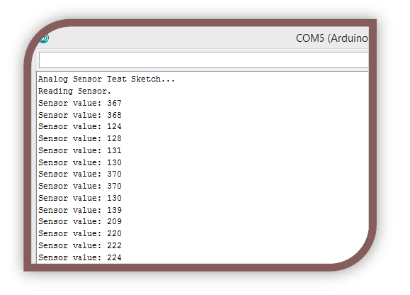
Expected Output:
In the example above I used a 3-pin photoresistor (light) Sensor. The reading changes as I shine light on it. Have a play with different modules and take note if they respond to stimuli the way you thought they would.
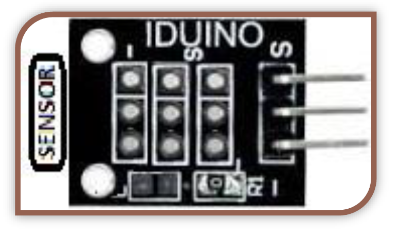
MODULES – The 3-pin Digital Sensor Module
Voltage (Min-Max): 3-5V
# of Pins used: 3
Type of pins used: DIGITAL
Which Sensors does this apply to?
This applies to any sensor that has 3 pins and puts either a 5V (HIGH) or 0V (LOW) signal depending on the sensor state.
In the 37-in-1 kit this includes:
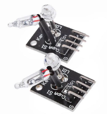
- Tilt Switch
- Activates when the mercury moves to one end of the tube.
- Ball Switch
- Activates when the ball moves to one end of the tube.
- Mini Reed
- Activates when a magnet moves near one end of the tube.
- Tracking
- Activates when it senses an object within the calibrated distance.
- Light Blocking
- Activates when something blocks the beam of light between the 2 parts of the component.
Why are a lot of sensors so similar to use?
A common feature of electronic components is their ability to conduct or block electricity depending on outside influences. We use this as a way to measure our world.
- The sensor will have an input voltage, and ground connection and a pin that will output a value that is either the input or 0V.
- The pins will be labeled, and may not always be in the same order, so hook them up the way they are labelled even if it is slightly different to this guide. This guide is accurate for any sensor mounted on the board pictured on the section-intro above.
By making these modular boards able to take any sensor essentially and have hobbyists simply able to use it, regardless of having read the fact-sheet etc is amazing! Arduino is simply an amazing system.
The pins on these modules are as follow:
- S: Signal/Sensor Out
- This pin will output either 0v or +(Voltage in) which is directly related to the measurement of the sensor. This pin is connected to any Digital Pin.
- +: Vs/ Positive supply (5V max)
- The middle pin is for +5V or +3.3V. This will power the sensor and give a reference voltage for the output. This will be connected to +5V or +3.3V on the Arduino.
- -: GND
- The final leg is GND and allows a return path for current, completing the circuit. This should be connected to your Arduino GND.
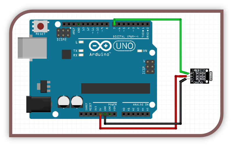
Example Circuit:
In this configuration we use “digitalRead(7)” to get the Digital value.
Example Code:
//----Begin Code (copy from here)----
/*
Set the variables below to the desired values, there are also predefined
functions at the bottom of the sketch you can use in your own projects
*/
//Includes:
//Variables:
int delayVal = 500; //Time to delay between reads.
int debug_values = 1; //1 = show values in serial / 0 = hide.
void setup() {
// put your setup code here, to run once:
Serial.begin(9600); //Open serial connection
Serial.println("Analog Sensor Test Sketch...\nReading Sensor.");
}
void loop() {
// put your main code here, to run repeatedly:
while (digitalRead(7) == HIGH) { //While the pin is HIGH
pinHigh(); //Trigger the pinHigh function. Put your code to be executed there.
if (debug_values) { //If we have set the debug variable to 1 and the pin is HIGH
Serial.println("PIN HIGH"); //Print the debug string "PIN HIGH" to the serial port
delay(delayVal);
}
pinLow();
if (debug_values) { //If we have set the debug variable to 1 and the pin is HIGH
Serial.println("PIN LOW"); //Print the debug string "PIN HIGH" to the serial port
}
//delay
delay(delayVal); //Delay for the period we defined
}
//Custom functions
void pinHigh() {
//All actions in this function will be performed every loop that the sensor value is HIGH
}
void pinLow() {
//All actions in this function will be performed every loop that the sensor value is LOW
}
//----End Code (copy to here)----
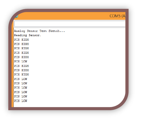
Expected Output:
In the example above I used a 3-pin mini reed (magnetic switch) Sensor. The reading changes as I move a magnet near it. Have a play with different modules and take note if they respond to stimuli the way you thought they would.
MODULES – The Analog/Digital Sensor Module
Voltage (Min-Max): 3-5V
# of Pins used: 4
Type of pins used: MIXED
Which Sensors does this apply to?
This applies to any sensor that is mounted on this type of board, in the 37-in-1 kit these include:
- Flame Sensor
- Detects the IR output of a naked flame.
- Linear Hall
- Measures magnetic fields.
- Big Sound
- A microphone, measures sound waves.
- Touch
- A touch sensor. Detects human skin contact.
- Small Sound
- A microphone, measures sound waves.
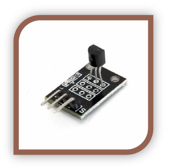
- Digital Temp
- Measures temperature using a digital thermometer.
- Tracking
- Essentially measures reflectivity, although people come up with very interesting uses for these. This module has only 3 pins, essentially the analog out is removed. You have digital + and gnd.
- Reed Switch
- This is a switch that is activated by holding a magnet near it. Open or closed only.
Why are a lot of sensors mounted on the same type of board?
This board is commonly found with analog sensors, as it gives them analog or digital output as required. They can be used in a few ways.
- You can read either the digital HIGH or LOW to determine if the value is above a threshold. This is an example of using it as a digital module.
- You can read the voltage on the analog out pin to get the actual value from the sensor. This is an example of using it as an analog module.
- Finally, you could set the Arduino to log the data, but only if the value is above or below the threshold. This is extremely handy.
By making these modular boards able to take any sensor essentially and turn it into a digital AND analog sensor without any major design work is amazing, and lots of companies took advantage of the design and released their own. The board also features a power LED and a status LED. The status LED shows if the digital output is triggered yet or not. This is extremely useful in debugging and setting thresholds.
The pins on these modules are as follow:
- AO: Analog Out
- This pin will output a voltage between 0v and + which is directly proportionate to the measurement of the sensor. This pin is connected to an analog in.
- G: Ground
- This pin is ground, or 0V. This Pin is connected to the Arduino ground.
- +: Positive Supply
- This pin is the positive supply for the module. We generally use 5 volts but there are other logic levels such as the common 3.3v. The analog out will be between 0v and this voltage.
- DO: Digital Out
- This pin is connected through the IC on the board and will output a HIGH or LOW depending on the state of the module. We adjust the blue variable resistor to change the trigger level of this.
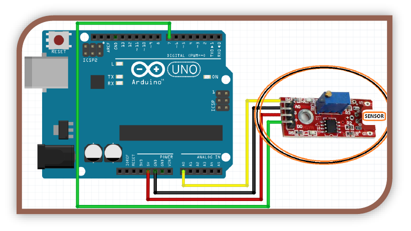
Example Circuit:
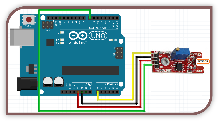
In this configuration we use “analogRead(A0)” to get the analog value, and to get the digital value we do a “digitalRead(7)”. Remember to gently turn the screw in the top of the blue variable resistor to adjust the sensitivity of the digital output.
Example Code:
//----Begin Code (copy from here)----
/*
Modify these variables to change parameters.
At the bottom of the code there are functions that are activated based on the sensor readings.
Add your own code inside these functions if you wish to use this code as a starting point.
The code is well-commented, so you should be able to follow easily.
----By Tyson Popynick 2016 - Free to modify or use unrestricted without credit or remuneration. ----
*/
//Variables:
int debug_showDigital = 0; //Show digital result in serial output?
int debug_showAnalog = 1; //Show analog result in serial output?
int timeDelay = 500; //Time to wait between readings. 1000 = 1 second.
int thresholdVal = 500; //Threshold level for triggers
void setup() {
// put your setup code here, to run once:
Serial.begin(9600); //Start serial communication with the Arduino
Serial.println("Arduino Analog/Digital module sketch...\nSerial Started."); //The arduino sends this through the serial monitor to show it is ready.
pinMode(7, INPUT); //Set the digital pin to input. Analog pins are automatically input.
}
void loop() {
//Read the sensor and store the values.
int digitalVal = digitalRead(7); //Read Digital pin and store result
int analogVal = analogRead(A0); //Read analog pin and store result
//Trigger any relevant functions
if (digitalVal == HIGH) { //Digital result = 1
highTrigger();
}
if (digitalVal == LOW) { //Digital result = 0
lowTrigger();
}
if (analogVal >= thresholdVal) { //Value above or equal to threshold
analogHigh(analogVal);
}
if (analogVal < thresholdVal) { //value lower than threshold
analogLow(analogVal);
}
//Debug output
if (debug_showDigital) { //If the debug_showDigital variable is set to 1 output data to serial.
Serial.print("Digital Result: ");
Serial.print(digitalVal);
if (debug_showAnalog) {
Serial.print(" ");
}
else {
Serial.print("\n");
}
}
if (debug_showAnalog) { //If the debug_showAnalog variable is set to 1 output data to serial.
Serial.print("Analog Result: ");
Serial.println(analogVal);
}
//Delay
delay(timeDelay); //Wait for specified period, then repeat.
}
//Custom Functions
void highTrigger() { //Code inside this function is run if the sensor is HIGH or "triggered"
}
void lowtrigger() { //Code here is run if the sensor is LOW or "not triggered"
}
void analogHigh(int value) {
//The code in here will be run if the analog result is higher than the threshold you set in the variable section at the top of this code
}
void analogLow(int value) {
//The code in here will be run if the analog result is higher than the threshold you set in the variable section at the top of this code
}
//----End Code (copy to here)----
Expected Output:
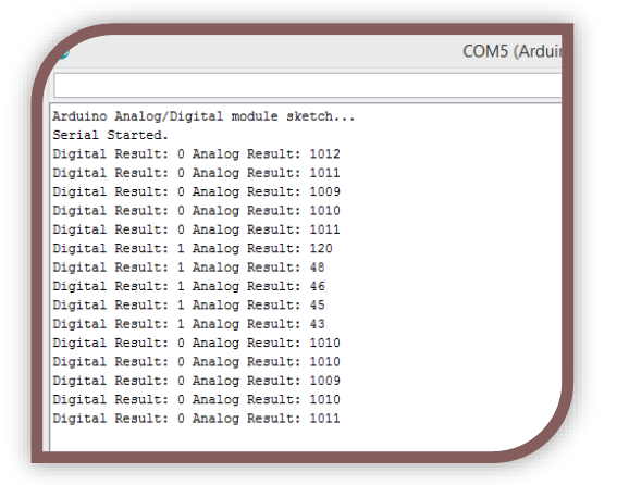
In the example above I used a Analog/Digital Sensor. The reading changes as I light a flame near it. Have a play with different modules and take note if they respond to stimuli the way you thought they would.
MODULES – Button Module
Voltage (Min-Max): 3-5V
# of Pins used: 3
Type of pins used: DIGITAL
How hard could it be to use a button?
Surprisingly, buttons are not as simple as they would seem in a digital circuit like this. If we just read the raw button data we will get multiple press events because the Arduino checks the button faster than we can let it go.
How do we fix that?
Essentially we simply store the last time we had a button press, if there has been a minimum of x mS since then, we can process the button data...otherwise it is not a clean press. This is called debouncing.
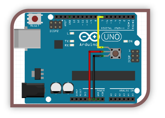
Example Circuit:
Example Code:
//----Begin Code (copy from here)----
//Includes:
//Variables:
int debounceMe = 1; //Change this to a 0 to see what its like without the debouncing
int lastState = 0; //store the previous button state so we know when the button has been pushed and released.
int lastDebounce = 0; //Store the time we last triggered
int debounceDelay = 100; //min time between presses
int buttonState = 0; //store the state of the button
void setup() {
// put your setup code here, to run once:
pinMode(7, INPUT);
Serial.begin(9600);
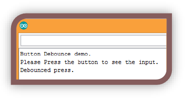
Serial.println("Button Debounce demo.\nPlease Press the button to see the input.");
}
void loop() {
//Read button and store result
lastState = buttonState;
buttonState = digitalRead(7);
if (debounceMe == 0) { //If debouncing is not enabled
if (buttonState == 1) {
Serial.println("Button Released"); //Just send the raw data to the serial window
}
else {
Serial.println("Button Pressed"); //Just send the raw data to the serial window
}
}
else { //If debouncing is enabled
if (buttonState == 0 && (lastDebounce + debounceDelay) <= millis() && lastState == 1) { //if the button is pressed & it has been longer than the delay & the button was previously not held in
Serial.println("Debounced press."); //success, this is a debounced press
lastDebounce = millis(); //reset the last debounce timer so we know when to trigger again
cleanPress(); //trigger our function to perform our actions.
}
}
}
//Custom Functions
void cleanPress() {
//This is triggered when a clean button press is detected. Place your code to execute on a clean press here.
}
//----End Code (copy to here)----
Expected Output:
You should see the temperature regularly print in the serial output window. This sensor is very accurate also.
MODULES – Buzzer Module
Voltage (Min-Max): 3-5V
# of Pins used: 2
Type of pins used: DIGITAL
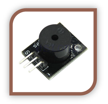
What is a Buzzer?
There are a few types of buzzers in the wild, there is the Active type and the Passive type.
- Active
- This type of buzzer will contain its own oscillator, which means you simply need to provide it with 5V and it will make a sound. The oscillator will turn the input voltage off and on very fast, producing a tone. The pitch can be varied with PWM.
- Passive
- This type of buzzer has no oscillator, and if you apply a DC current it will simply make a click sound as the diaphragm moves to its limit and stays there. If you apply a PWM signal it will make a sound, because PWM turns the supply on and off in a similar way to an oscillator.
What is it useful for?
Buzzers are very useful to alert the user to events, and the passive buzzers are really just small speakers. Piezoelectric speakers are also similar, and apart from the specifications, normal speakers are controlled the same way. Of course, if you want to hear meaningful sound you should purchase a sound module. Aus electronics direct sell a range of modules, including one that can record and play back sounds!
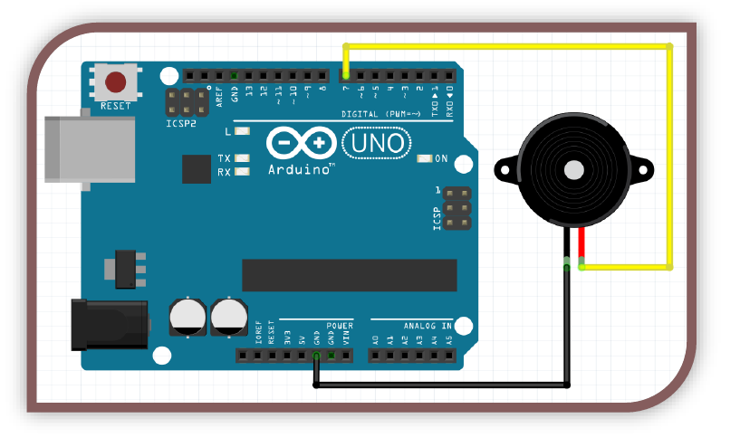
Why are there 3 pins on the module board, but we are only using 2 of them?
We only need 2 pins for a buzzer or speaker, however the module boards have 3 pins. The middle pin is not connected in this case. S is +5V and – is GND.
Example Circuit:
Example Code:
//----Begin Code (copy from here)----
//Includes:
//Variables:
delayTime = 500; //Time to play each pitch for. 1000 = 1 second.
void setup() {
// put your setup code here, to run once:
pinMode(7, OUTPUT); //Rotary Encoder pin CLK
Serial.begin(9600);
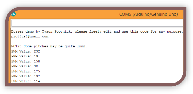
Serial.println("Buzzer demo by Tyson Popynick, please freely edit and use this code for any purpose.\nprot3us1@gmail.com\n\nNOTE: Some pitches may be quite loud.");
}
void loop() {
int PWM = random(0,255);
analogWrite(7, PWM);
delay(delayTime);
}
//----End Code (copy to here)----
Expected Output:
MODULES – 18B20 Digital Temp Module
Voltage (Min-Max): 3-5V
# of Pins used: 3
Type of pins used: DIGITAL
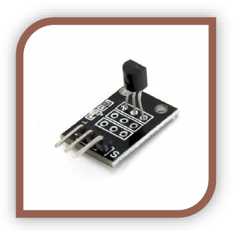
How is this different to the other TEMP sensors?
The other sensors are fairly simple analog components, their value changes based on temperature. This sensor is digital, it has a unique serial number printed on it, and can be addressed using this (or other methods). You can change settings such as precision etc on the device using the libraries also. We will not cover that in this guide, however you could google search for “18B20 settings Arduino” and find good info.
Why is it better?
1Wire means we can use a massive amount of these sensors on 1 pin of the Arduino…We could theoretically attach 100 of them to the Arduino, and check each in sequence..we would only have used a single pin on the Arduino, this is incredible. There are other great features too, however we will move along.
Example Circuit:
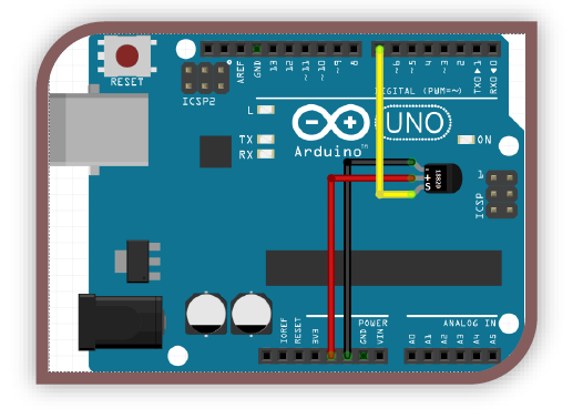
Example Code:
//----Begin Code (copy from here)----
//Includes:
#include <OneWire.h> //includes the functions needed to communicate with the 1-wire protocol
#include <DallasTemperature.h> //includes conversion functions from F to C etc, as well as the actual code to talk to the sensor.
//Variables:
OneWire oneWire(7); //Set the One Wire Data bus on pin 7.
DallasTemperature sensor(&oneWire); //This is passing a reference to the sensor object. This isnt commonly needed.
void setup() {
// put your setup code here, to run once:
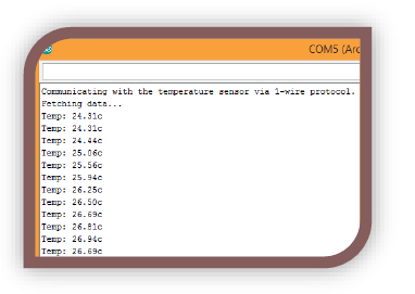
Serial.begin(9600);
Serial.println("Communicating with the temperature sensor via 1-wire protocol. \nFetching data...");
sensor.begin(); //Begin talking to the sensor
}
void loop() {
// put your main code here, to run repeatedly:
sensor.requestTemperatures(); //Request temperatures from the sensor
Serial.print("Temp: "); //print "Temp: "
Serial.print(sensor.getTempCByIndex(0)); //populate the temperature reading.
Serial.println("c"); //print "Temp: "
}
//----End Code (copy to here)----
Expected Output:
You should see the temperature regularly print in the serial output window. This sensor is very accurate also.
MODULES – The Heartbeat Detector Module
Voltage (Min-Max): 3-5V
# of Pins used: 3
Type of pins used: ANALOG
What is the active component in this module?
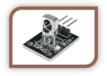
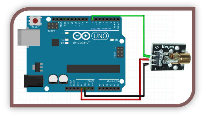
This module is built around an IR LED and an IR receiver. The IR led shines a certain wavelength of light through your finger. Our skin allows IR to pass through, but our blood looks very different to an IR sensor when it has oxygen present vs no oxygen present. In this way, we can sense when the heart beats by watching for the changes in opacity.
The sensor takes care of most of the hard part. We need to shield as much light from the sensor as we can for it to work properly. I wrapped mine in electrical tape, however you can use cardboard, paper, plastic or any other material that will stop external light interfering with the sensor.
Example Circuit Layout:
Example Circuit Code:
//----Begin Code (copy from here)----
//Includes:
//Variables:
double a = 0.75; //Alpha
double c = 0.0; //Difference
int period = 20; //Delay period
void setup() {
// put your setup code here, to run once:
Serial.begin(9600);
pinMode(13, OUTPUT);
}
void loop() {
// put your main code here, to run repeatedly:
static double oldVal = 0;
static double oldC = 0;
int rawVal = analogRead(A0);
double val = a*oldVal+(1-a)*rawVal;
c = val - oldVal;
int temp = (c<0.0&&oldC>0.0);
digitalWrite(13, temp);
if (temp) {
Serial.println("Beat.");
}
else {
Serial.print(".");
}
oldVal = val;
oldC = c;
delay(period);
}
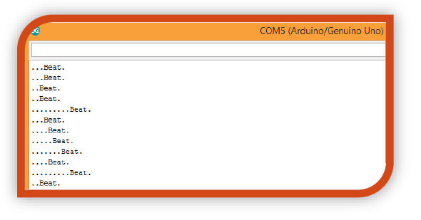
Expected Output:
The code shows an output in 2 states, one state outputs “.”, the other outputs “BEAT”. On a period there is no beat detected, there will be a succession of periods until a beat is detected, then the output changes to BEAT. In this way you can see patterns easily by looking at the line length in serial output as shown to the right.
MODULES – IR Receiver and Transmitter Module
Voltage (Min-Max): 3-5V
# of Pins used: 3
Type of pins used: DIGITAL
What is an IR Receiver and Transmitter sensor?
The IR receiver module will accept and decode IR remote control signals so we can tell which button has been pressed on a remote. The transmitter is an IR LED, which is able to be pulsed at the correct frequencies to send commands as if it WAS a TV remote. For the purpose of this demo, I will show you HOW to send IR data, and HOW to receive it…however as there are many protocols available you will have to research the type of receiver you are trying to communicate with.
What is it useful for?
We can use remote controls as inputs using the receiver and we can make our own remotes with the IR LED!
Install the library:
Follow the instructions in the library installation section, and install the following library. Don’t forget to include the library once you have installed it! You will need to delete the following folder from your Arduino directory:
C:\Program Files (x86)\Arduino\libraries\RobotIRremote
This library interferes with the IR remote library, and if you need it in the future you can simply get it again through the manager.
For this portion of the guide I will include 2 separate diagrams and code. One for the transmitter and one for the receiver. You can combine them or keep them separate depending on your project!
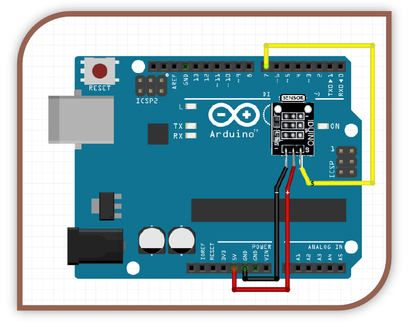
Example Circuit (receiver):
 Example Code(receiver):
//----Begin Code (copy from here)----
#include <IRremote.h> //Note you will need to delete a built in library that comes with the arduino IDE that has a conflict with this library.
//Please delete the ir robot library.
//Variables:
IRrecv irrecv(7); //Set up the IR Reciever, call it irrecv and attach it to the correct pin
decode_results results; //Set up a variable to hold the results
void setup()
{
// put your setup code here, to run once:
Serial.begin(9600);
irrecv.enableIRIn(); // Start the receiver
}
void loop() {
// put your main code here, to run repeatedly:
if (irrecv.decode(&results)) {
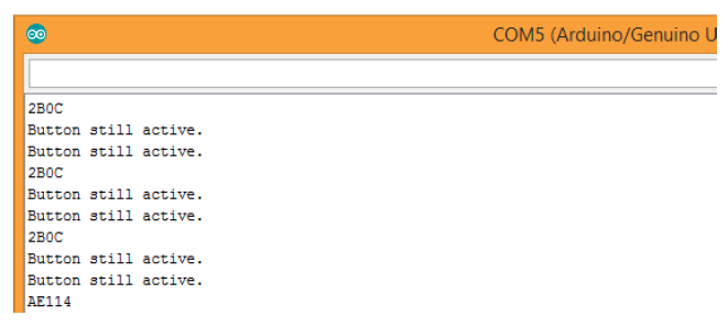
String tmp = (String)results.value; //Read and store the incoming code from the IR receiver
if (tmp == "4294967295") //This value tells the Arduino that the previous button is still active.
{
Serial.println("Button still active."); //Report to the serial monitor the last button was still held down
}
else {
Serial.println(results.value, HEX); //A new button has been pressed with the value shown.
}
irrecv.resume(); // Receive the next value
}
}
//----End Code (copy to here)----
Expected Output(receiver):
Example Circuit (transmitter):
Example Code(transmitter):
//----Begin Code (copy from here)----
//Includes:
#include <IRremote.h>
//Variables:
IRsend irsend;
void setup()
{
Serial.begin(9600);
}
void loop() {
irsend.sendSony(0xa90, 12); //Code to send. You will need to use the receiver to collect codes
Serial.println("Sent Code.."); //In case you want to see when the pulses are sent
digitalWrite(13, HIGH); //Also light the LED connected to pin 13 on the arduino board
delay(250); //Small delay to allow the LED to flicker
digitalWrite(13, LOW); //turn the LED off
delay(5000); //5 second delay between each send
}
//----End Code (copy to here)----
Expected Output(transmitter):
Once you have collected the codes to send by aiming your remote at the receiver and recording them, you can send them. You should see the same function performed by the device when the Arduino sends the signal…
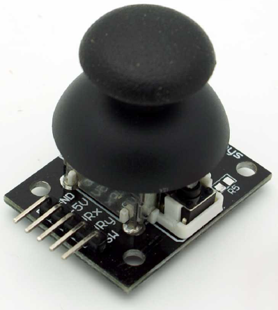
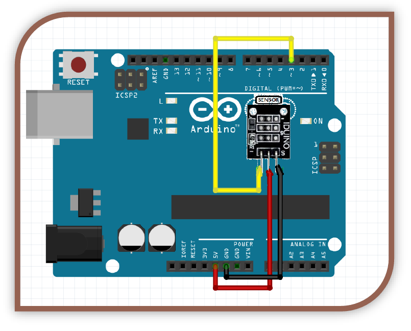
MODULES – The JoyStick Module
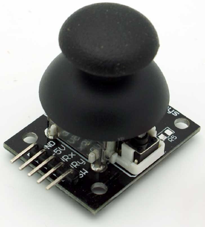
What is the active component in this module?
This module is built around 2 potentiometers and a tactile button. A voltage is passed in to each potentiometer, which then outputs a value that is directly related to the position of the stick. We can then read these values and use them to control our projects. The button will need to be de-bounced as always to prevent multiple readings.
Example Circuit Code:
//----Begin Code (copy from here)----
/*
Joystick module example code created by Tyson Popynick (prot3us1@gmail.com) for Aus Electronics Direct.
Outputs are found at the bottom of the sketch, dead zone, null zone and de-bounce time can be set by user.
Debug output verbosity can be set by user.
Gives the following outputs:
Button clicked
Button held + duration
Direction moved + distance moved
*/
//Includes:
//Variables:
//Non changeable variables:
int joyInXPin = A0; //X-Axis input pin
int joyInYPin = A1; //Y-Axis input pin
int joyInButton = 7; //Button input pin
int debounceState = 0; //Variable to store the debounce state
int isHeld = 0; //Variable to store the last debounce state
unsigned long lastDebounce = 0; //Variable to store the last time the button was pressed
int valX = 0; //Variable to store the value of the X-axis in
int valY = 0; //Variable to store the value of the Y-axis in
int lastX = 0; //Variable to hold the last X value
int lastY = 0; //Varialble to hold the last Y value
//Changeable Variables, edit the values below to tweak operation.
unsigned long debounceTime = 100; //Minimum time to wait between button state changes
int DEAD_ZONE = 5; //Joystick dead zone, gives a tiny null area in the middle of the stick to stop ghost values.
int nullX = 500; //average output of X axis at center
int nullY = 528; //average output of Y axis at center
//debug settings
int debug_rawXY = 0; //Should we output raw X/Y Data to serial? (1 = Show / 0 = hide)
int debug_rawButton = 0; //Should we output raw button Data to serial? (1 = Show / 0 = hide)
int debug_processedButton = 1; //Should we output processed button Data to serial? (1 = Show / 0 = hide)
int debug_processedJoystick = 1; //Should we output processed joystick data to serial? (1 = show / 0 = hide)
void setup() {
// put your setup code here, to run once:
Serial.begin(9600);
}
void loop() {
// put your main code here, to run repeatedly:
//Joystick input
lastX = valX;
lastY = valY;
valX = analogRead(joyInXPin);
valY = analogRead(joyInYPin);
if (valX > nullX && (valX - nullX) >= DEAD_ZONE) {
//Up
joyUp(valX - nullX);
}
if (valX < nullX && (nullX - valX) >= DEAD_ZONE) {
//Down
joyDown(nullX - valX);
}
if (valY < nullY && (nullY - valY) >= DEAD_ZONE) {
//Left
joyLeft(nullY - valY);
}
if (valY > nullY && (valY - nullY) >= DEAD_ZONE) {
//Right
joyRight(valY - nullY);
}
//Print the values to the Serial Output if we have the debug variable set to 1
if (debug_rawXY == 1) {
Serial.print("X Axis: ");
Serial.print(valX);
Serial.print(" Y Axis: ");
Serial.println(valY);
}
//Button input
if (debounceState == 1) {
if ((millis() - lastDebounce) >= debounceTime) {
if (digitalRead(joyInButton) == HIGH && isHeld == 0) {
//Button Released?
if (debug_rawButton == 1) {
Serial.println("Button Clicked with no hold.");
}
debounceState = 0;
buttonClicked();
}
if (digitalRead(joyInButton) == HIGH && isHeld == 1) {
//Button Released?
if (debug_rawButton == 1) {
Serial.print("Button Released after holding for: ");
Serial.print(millis() - lastDebounce);
Serial.println(" mS.");
}
debounceState = 0;
isHeld = 0;
buttonReleased(millis() - lastDebounce);
}
if (digitalRead(joyInButton) == LOW) {
//Button still pressed??
isHeld = 1;
if (debug_rawButton == 1) {
Serial.print("Button held for: ");
Serial.println(millis() - lastDebounce);
}
}
}
}
if (debounceState == 0) {
if (digitalRead(joyInButton) == LOW) {
//Button pressed?
debounceState = 1;
lastDebounce = millis();
}
}
} //Loop end
//------------------------------------------------------------------------------------------------------------
/*
The sections below all contain an area that looks like this:
//Actions to perform when this is triggered
//End actions to perform
Feel free to add any actions in between those lines, that you would like to perform when that particular event
is triggered.
*/
//------------------------------------------------------------------------------------------------------------
void buttonClicked() {
//This is called when the button is clicked without holding.
if (debug_processedButton == 1) {
Serial.println("Button Click event fired.");
}
//Actions to perform when this is triggered
//End actions to perform
}
void buttonReleased(int lengthHeld) {
//This is called when the button is released after holding. lengthHeld contains duration in mS.
if (debug_processedButton == 1) {
Serial.print("Button Held event fired, length of hold was: ");
Serial.print(lengthHeld);
Serial.println(" Milliseconds.");
}
//Actions to perform when this is triggered
//End actions to perform
}
bool buttonHeld() {
//This is called to check if the button is still being held. True or 1 if its held, False or 0 if not.
if (isHeld == 1) {
return 1;
}
else {
return 0;
}
//Actions to perform when this is triggered
//End actions to perform
}
void joyUp(int moveAmt) { //Called when the joystick is moved "upwards", with the value stored in moveAmt
moveAmt = constrain(moveAmt, 0, 495);
if (debug_processedJoystick == 1) {
Serial.print("Joystick moved Up.");
Serial.println(moveAmt);
}
//Actions to perform when this is triggered
//End actions to perform
}
void joyDown(int moveAmt) { //Called when the joystick is moved "downwards", with the value stored in moveAmt
moveAmt = constrain(moveAmt, 0, 495);
if (debug_processedJoystick == 1) {
Serial.print("Joystick moved Down.");
Serial.println(moveAmt);
}
//Actions to perform when this is triggered
//End actions to perform
}
void joyLeft(int moveAmt) { //Called when the joystick is moved "left", with the value stored in moveAmt
moveAmt = constrain(moveAmt, 0, 495);
if (debug_processedJoystick == 1) {
Serial.print("Joystick moved Left.");
Serial.println(moveAmt);
}
//Actions to perform when this is triggered
//End actions to perform
}
void joyRight(int moveAmt) { //Called when the joystick is moved "right", with the value stored in moveAmt
moveAmt = constrain(moveAmt, 0, 495);
if (debug_processedJoystick == 1) {
Serial.print("Joystick moved Right.");
Serial.println(moveAmt);
}
//Actions to perform when this is triggered
//End actions to perform
}
//----End Code (copy to here)----
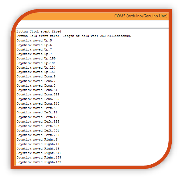
Expected Output:
The code provides output to debug the module, as well as the ability to be easily modified to perform any actions the user wants based on input.
MODULES – Laser Module
Voltage (Min-Max): 3-5V
# of Pins used: 3
Type of pins used: DIGITAL
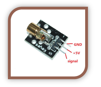
Is this a REAL LASER?
This is a real laser diode, the kind you get in pointers and keychains etc. It will not cause permanent eye damage, however it can dazzle and cause washout for a fair period of time, don’t look into the beam and try to avoid it reflecting into your eye for any lengthy periods of time (> 1 sec).
Why would I need a LASER?
There are multiple uses, the simplest being a laser tripwire system. Use the LASER emitter, shining onto an LDR (photoresistor), when the light level drops rapidly and significantly something broke the beam of light, trigger the alarm.
ou can also make laser microphones etc with these modules, they will not cut however.
Example Circuit:
Example Code:
//----Begin Code (copy from here)----
//Includes:
#include <math.h> //contains common math functions
//Variables:
int delayTime = 1000; //Delay time. 1000 = 1 second.
void setup() {
// put your setup code here, to run once:
pinMode(7, OUTPUT); //Set pin 7 to output.
}
void loop() {
// put your main code here, to run repeatedly:
digitalWrite(7, HIGH); //Set pin 7 to HIGH
delay(delayTime); //wait defined time period before repeating
digitalWrite(7, LOW); //Set pin 7 to LOW
delay(delayTime); //wait defined time period before repeating
}
//----End Code (copy to here)----
Expected Output:
The LASER should turn on, then off repeatedly. This shows you how to control it…now it is up to you to make cool projects with it!

MODULES – The Magic Light Cup Module
What is the active component in this module?
This module is a red LED paired with a mercury tilt switch. The components are discrete, that is – they share a power connection, but do not influence each other without the Arduino. Essentially this module was made for a very specific purpose – a toy in China where you have 2 cups, and when you tilt one it “empties” into the other.
Essentially it is supposed to be similar to pouring the light from one cup to the other. The cup being the LED.
In reality, we simply check if the tilt switch has changed orientation. If it has we increase brightness from 1 LED to the other. We then reverse the process when it is tilted the other way. What we get is basically 2 LEDs controlled by tilt sensors. I only use one of the tilt sensors, you could use both if you wish.
When the tilt sensor changes position LED A begins decreasing brightness, while LED B increases brightness. That is the whole module.
Example Circuit Layout:
Example Circuit Code:
//----Begin Code (copy from here)----
//Includes:
//Variables:
int light1Val = 0;
int light1State = 0;
int merc1Val = 0;
int merc1LastVal = 0;
int light2Val = 0;
void setup() {
// put your setup code here, to run once:
Serial.begin(9600);
pinMode(2, INPUT);
pinMode(3, OUTPUT);
}
void loop() {
// put your main code here, to run repeatedly:
merc1Val = digitalRead(2);
if (merc1Val == 1 && merc1LastVal == 0) {
light1Val -= light1Val / 8;
light2Val += light2Val / 8;
light1State = 1;
merc1LastVal = 1;
}
if (merc1Val == 0 && merc1LastVal == 1) {
light1Val += light1Val / 8;
light2Val -= light2Val / 8;
light1State = 0;
merc1LastVal = 0;
}
if (light1State) {
light1Val--;
light1Val = constrain(light1Val, 0, 255);
light2Val++;
light2Val = constrain(light2Val, 0, 255);
analogWrite(3, light1Val);
analogWrite(5, light2Val);
}
else {
light1Val++;
light1Val = constrain(light1Val, 0, 255);
light2Val--;
light2Val = constrain(light2Val, 0, 255);
analogWrite(3, light1Val);
analogWrite(5, light2Val);
}
}
//----End Code (copy to here)----
Expected Output:
The output of this project is not actually text-based. You should see one LED get brighter as the other dims. Tilt the active module the other way to see them reverse. Set it up in plastic cups so the light seems to “fill” them.
This module has a specific use which makes it difficult to use in your own projects. Remember you can access the LED and mercury switch separately, they may be more useful like that than they are together.
MODULES – Multi-LED Packages Module
Voltage (Min-Max): 3-5V
# of Pins used: 3
Type of pins used: DIGITAL
Which LEDs does this apply to?
This part of the guide applies to any MULTI-LED PACKAGES Module.
In the 37-in-1 kit this includes:
- 7 color flash
- Flashes through 7 colors, then fades between them. You simply apply 5v. This is a 2 terminal component.
- Two-color (Smaller)
Pins as follow:
S = + (positive)
Mid = - (Yellow Turns on)
- = - (Orange turns on)
- Two-color (Larger)
- Should be similar to above, unfortunately mine was DOA.
7-color Flash:
Although it is not exactly like the others we included it here seeing as it doesn’t fit anywhere else. Simply attach GND to the – pin, and +5V to the S pin, and this module will automatically cycle through 7 colors, then slowly fade between them.
What would this be useful for?
With these LED packages we can wire them in such a way that the Arduino can pull either pin LOW or HIGH in order to turn on the appropriate LED. These are not as useful now as they once were, seeing as they take 2 digital pins, however you may find a use for them in projects!
We have included the 7 color flash module in this part of the guide as it doesn’t really fit in anywhere and there is no point making its own section.
Example Circuit:
Example Code:
//----Begin Code (copy from here)----
//Includes:
//Variables:
void setup() {
// put your setup code here, to run once:
Serial.begin(9600);
pinMode(7, OUTPUT);
pinMode(6, OUTPUT);
}
void loop() {
// put your main code here, to run repeatedly:
digitalWrite(7, HIGH);
digitalWrite(6, LOW);
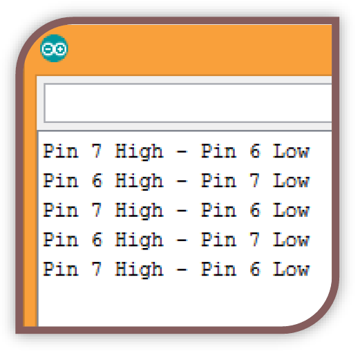
Serial.println("Pin 7 High - Pin 6 Low");
delay(1000);
digitalWrite(6, HIGH);
digitalWrite(7, LOW);
Serial.println("Pin 6 High - Pin 7 Low");
delay(1000);
}
//----End Code (copy to here)----
Expected Output:
The expected output is what will essentially appear as a flashing LED, it seems a bit plain, but it is a result!
MODULES – Relay Module
Voltage (Min-Max): 3-5V
# of Pins used: 3
Type of pins used: DIGITAL
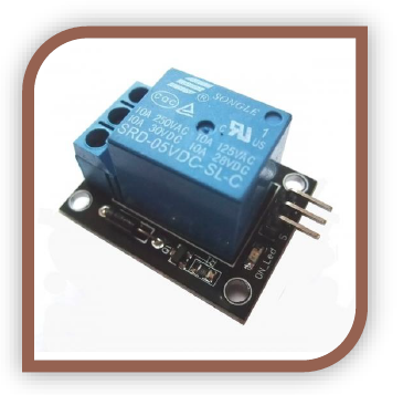
What IS a relay?
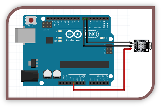
A relay is a device that is able to switch extremely high voltages and currents on or off with relatively small voltage and current. In other words, you could use a relay to turn a 240V appliance on, even though the Arduino is only running at 5 volts.
A relay is an electromechanical switch. That means it has physical metal contacts, literally strips of metal that are on a rocker arm with a spring and a coil. When we apply power to the coil we turn it into an electromagnet, which pulls the contacts to the other side. At this point the NO (normally open) output becomes closed, and the NC (normally closed) output becomes open. (Closed meaning it is conducting, and open meaning it is not conducting).
Why would I need a relay?
People use them for many reasons, from high voltage uses as I mentioned, home automation, large amplifiers, large loads like motors and induction coils etc can be isolated with relays also.
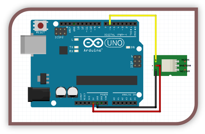
Example Circuit:
Example Code:
//----Begin Code (copy from here)----
//Includes:
//Variables:
int delayTime = 1500; //Delay time between switches
void setup() {
// put your setup code here, to run once:
Serial.begin(9600);
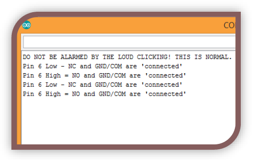
Serial.println("DO NOT BE ALARMED BY THE LOUD CLICKING! THIS IS NORMAL.");
pinMode(6, OUTPUT);
}
void loop() {
// put your main code here, to run repeatedly:
digitalWrite(6, LOW);
Serial.println("Pin 6 Low - NC and GND/COM are 'connected'");
delay(delayTime);
digitalWrite(6, HIGH);
Serial.println("Pin 6 High = NO and GND/COM are 'connected'");
delay(delayTime);
}
//----End Code (copy to here)----
Expected Output:
The expected output is what will essentially appear as a flashing LED, it seems a bit plain, but it is a result!
MODULES – The RGB LED Module
Voltage (Min-Max): 3-5V
# of Pins used: 4
Type of pins used: DIGITAL
Which LEDs does this apply to?
This part of the guide applies to any RGB LED Module.
In the 37-in-1 kit this includes:
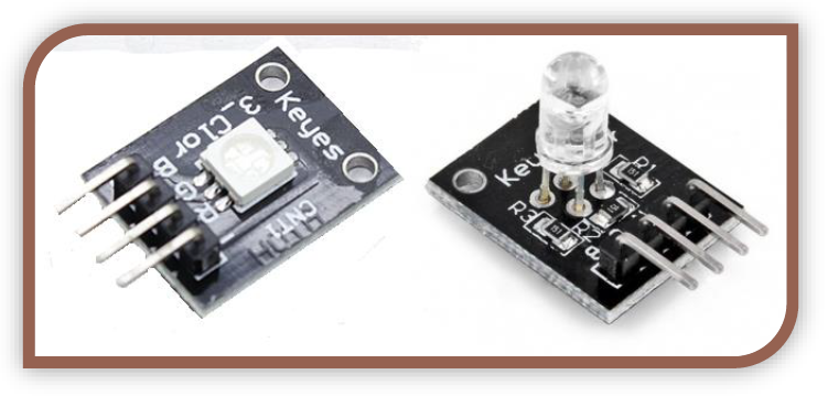
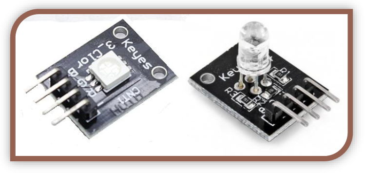
- RGB LED
- This is a standard LED through-hole package on a module board.
- SMD RGB
- This is a surface mount LED package mounted on a module board.
How can we make any color possible, with such a small component?
These RGB LED modules all contain 3 LEDs, a Red, a Blue and a Green. By varying the brightness of each color using PWM, we can mix the colors and make any color we desire. We will be making a sketch to run the LED through random colors, however once you have assembled the circuit you can always google “RGB LED Arduino projects” and see what projects other people have made with them! Also feel free to mess around with the RGB values and see what you get! As a bonus I decided to include some code to allow you to manually play with the colors. This is explained later on.
The pins on these modules are as follow:
- B: Blue
- This pin controls the blue LED in the module.
- R: Red
- This pin controls the red LED in the module.
- G: Green
- This pin controls the green LED in the module.
- -: GND
- The final leg is GND and allows a return path for current, completing the circuit. This should be connected to your Arduino GND.
Example Circuit:
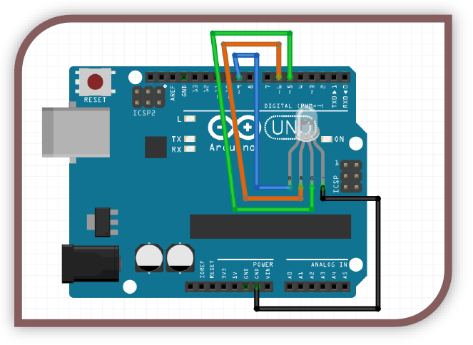
NOTE: This applies to the SMD module as well. The through hole module is pictured.
Example Code:
//----Begin Code (copy from here)----
//Includes:
//Variables:
int redPin = 6; //Pin that the red LED leg is connected to.
int greenPin = 5; //Pin that the green LED leg is connected to.
int bluePin = 9; //Pin that the blue LED leg is connected to.
int rVal = 0; //Variable to store the PWM value to run the red LED at.
int gVal = 0; //Variable to store the PWM value to run the red LED at.
int bVal = 0; //Variable to store the PWM value to run the red LED at.
String serialIn = ""; //Variable to store serial input from pc to arduino
int changed = 1; //variable to tell when the values have changed, so we dont flood the serial output with useless data.
int random_values = 0; //If set to 1 the channels will randomly change every period.
unsigned long lastRand = 0; //Store the last time we randomized.
int period = 1000; //period between randomizations. 1000 = 1 second.
void setup() {
// put your setup code here, to run once:
Serial.begin(9600);
Serial.print("RGB LED Test Code (C) Tyson Popynick. Free to use without notification, renumeration or attribution. \n(Although you are welcome to attribute if you wish).\n\nPlease do NOT look directly at the LED modules when they are powered, as they are extremely bright!\nEnter the following commands into the box above, then press enter to send.\n\nOne letter per send
please.\n\nR = Large increase to red channel. \nr = Small increase to red channel.\nG = Large increase to green channel. \ng = Small increase to green channel.\nB = Large increase to blue channel. \nb = Small increase to blue channel. \n! = Toggle randomised lights\n'.' to clear all channels.\n\n");
pinMode(redPin, OUTPUT);
pinMode(greenPin, OUTPUT);
pinMode(bluePin, OUTPUT);
}
void loop() {
// put your main code here, to run repeatedly:
//Serial In
if (Serial.available()) { //If there is a serial connection
serialIn = Serial.readString(); //store any incoming (from the pc to arduino) data
if (serialIn == "r") { //if we send the letter r (lowercase)
rVal += 10; //Increase red value by 10
}
if (serialIn == "R") { //if we send the letter R (uppercase)
rVal += 30; //Increase red value by 30
}
if (rVal >= 256) { //If the value goes above 255, reset to 0. (255 is max value for PWM)
rVal = 0;
}
if (serialIn == "g") { //if we send the letter g (lowercase)
gVal += 10; //Increase green value by 10
}
if (serialIn == "G") { //if we send the letter G (uppercase)
gVal += 30; //Increase green value by 30
}
if (gVal >= 256) { //If the value goes above 255, reset to 0. (255 is max value for PWM)
gVal = 0;
}
if (serialIn == "b") { //if we send the letter b (lowercase)
bVal += 10; //Increase blue value by 10
}
if (serialIn == "B") { //if we send the letter B (uppercase)
bVal += 30; //Increase blue value by 30
}
if (bVal >= 256) { //If the value goes above 255, reset to 0. (255 is max value for PWM)
bVal = 0;
}
if (serialIn == ".") { //if we send a "."
rVal = 0; //Clear all values
gVal = 0; //Clear all values
bVal = 0; //Clear all values
}
if (serialIn == "?") { //if we send a "?"
Serial.print("RGB LED Test Code (C) Tyson Popynick. Free to use without notification, renumeration or attribution. \n(Although you are welcome to attribute if you wish).\n\nPlease do NOT look directly at the LED modules when they are powered, as they are extremely bright!\nEnter the following commands into the box above, then press enter to send.\n\nOne letter per send please.\n\nR = Large increase to red channel. \nr = Small increase to red channel.\nG = Large increase to green channel. \ng = Small increase to green channel.\nB = Large increase to blue channel. \nb = Small increase to blue channel. \n! = Toggle randomised lights\n'.' to clear all channels.\n\n");
}
if (serialIn == "!") { //if we send a "!"
random_values = !random_values;
}
serialIn = "";
changed = 1;
}
//loop continues
if (random_values && (lastRand + period) <= millis()) {
rVal = random(0,255); //Randomize red channel
gVal = random(0,255); //Randomize green channel
bVal = random(0,255); //Randomize blue channel
lastRand = millis();
changed = 1;
Serial.println("Randomized! Send '!' to stop randomization or '?' for the command list.");
}
if (changed) {
Serial.print("Red: ");
Serial.print(rVal);
Serial.print(" Green: ");
Serial.print(gVal);
Serial.print(" Blue: ");
Serial.print(bVal);
Serial.print(" Randomize: ");
Serial.println(random_values);
changed = 0;
analogWrite(redPin, rVal);
analogWrite(greenPin, gVal);
analogWrite(bluePin, bVal);
}
}
//Custom functions
//----End Code (copy to here)----
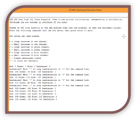
Expected Output:
The expected output in this project is a practical demonstration. The serial console window will give you instructions as to how to use it. Have a play! Double check you have all the pins correct, then upload the code and enjoy!
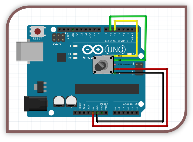
MODULES – Rotary Encoder Module
Voltage (Min-Max): 3-5V
# of Pins used: 5
Type of pins used:DIGITAL
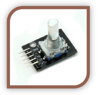
What is a rotary encoder?
A rotary encoder is a component which counts rotations. With a potentiometer, we can only turn so far before the knob will not turn any further. A rotary encoder does not have this problem, it can spin in either direction indefinitely. It can also be pushed in, functioning as a button. We have covered buttons before so we will focus on the rotary encoder for this tutorial. (essentially the SW pin is of course, just a normal button, treat it the same way as the button module.
What is it useful for?
It is useful for using one knob for an entire setup rather than independent controls for volume, pitch, balance etc for example.
Example Circuit:
Example Code:
//----Begin Code (copy from here)----
//Includes:
//Variables:
int val = 1;
int lastVal = 0;
int pos = 0;
void setup() {
// put your setup code here, to run once:
pinMode(5, INPUT); //Rotary Encoder pin CLK
pinMode(6, INPUT); //Rotary encoder pin DT
Serial.begin(9600);
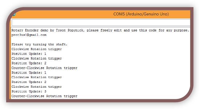
Serial.println("Rotary Encoder demo by Tyson Popynick, please freely edit and use this code for any purpose.\nprot3us1@gmail.com\n\nPlease try turning the shaft.");
}
void loop() {
//read rotary encoder
lastVal = val; //set lastVal to the old value
val = digitalRead(6); //set val to the new value read from the rotary encoder
if (val == 1 && lastVal == 0) { //if the new value and the old value are different the knob was turned
if (digitalRead(5) == 1) { //if the CLK channel is HIGH we have turned the knob clockwise.
pos++; //Increase the "position" variable for the output value measurement
CW_Click(); //call our function, where our code is executed down below the loop
}
else { //If the CLK channel is LOW then we turned the knob counter-clockwise
pos--; //Decrease pos counter
CCW_Click(); //Execute counter-clockwise click function so our event can fire.
}
pos_Update(pos); //Regardless of the direction, call the pos_Update function with the pos value.
//this way we can trigger our events regardless of whether we need a value or a direction.
}
}
//Custom Functions
void CW_Click() { //Triggered when the control is rotated clockwise
Serial.println("Clockwise Rotation trigger");
}
void CCW_Click() { //Triggered when the control is rotated counter clockwise
Serial.println("Counter-Clockwise Rotation trigger");
}
void pos_Update(int pos) { //Triggered every time the value changes, regardless of direction.
Serial.print("Position Update: ");
Serial.println(pos);
}
//----End Code (copy to here)----
Expected Output:
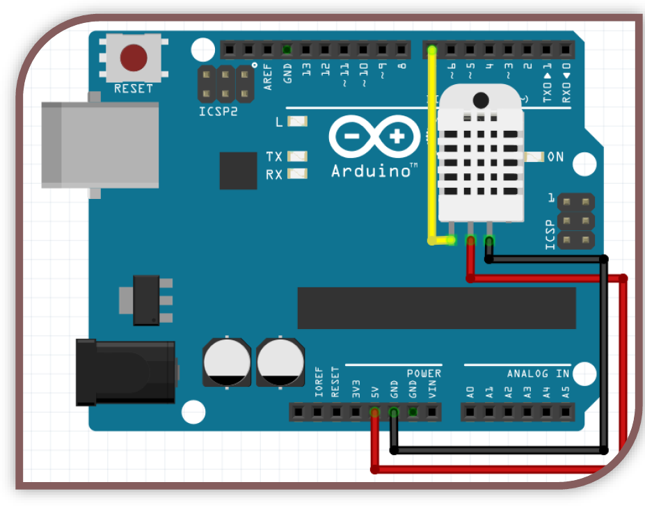
MODULES – Temp & Humidity Module
Voltage (Min-Max): 3-5V
# of Pins used: 3
Type of pins used: DIGITAL
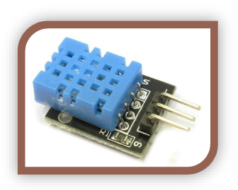
What is a Temp & Humidity sensor?
This is a digital sensor that will report the temperature, humidity and heat index on request. We will use a library to communicate via 1Wire with the sensor, and output the values!
What is it useful for?
You may want to monitor the weather, use it in an automation system for your heating or cooling, or remotely monitor the environment. There are a wide range of uses for this handly little sensor!
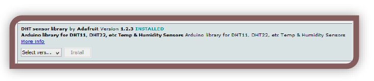
Install the library:
Follow the instructions in the library installation section, and install the following library. Don’t forget to include the library once you have installed it!
Example Circuit:
Example Code:
//----Begin Code (copy from here)----
//Includes:
#include <DHT.h> //Please make sure you search for, and install the DHT11 library.
//Refer to the section on installing libraries for assistance.
//Variables:
DHT dht(7, DHT11); //Initialize the object for the sensor. Pin 7 in this case, and a DHT11 sensor.
void setup() {
// put your setup code here, to run once:
Serial.begin(9600);
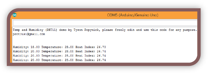
Serial.println("Temp and Humidity (DHT11) demo by Tyson Popynick, please freely edit and use this code for any purpose.\nprot3us1@gmail.com\n\n");
dht.begin(); //Begin communication with sensor
}
void loop() {
float humidity = dht.readHumidity(); //Read and store the humidity from the sensor
float temperature = dht.readTemperature(); //Read and store the temperature from the sensor (Celcius)
if (isnan(humidity) || isnan(temperature)) { //isnan means is not a number. If the data is coming back corrupt this should catch it
Serial.println("Error reading");
return; //This will return to the start of the loop without executing the code below.
}
float heatIndex = dht.computeHeatIndex(temperature,humidity,false); //Read and store the heat index from the sensor
Serial.print("Humidity: ");
Serial.print(humidity);
Serial.print(" Temperature: ");
Serial.print(temperature);
Serial.print(" Heat Index: ");
Serial.println(heatIndex); //Print all the values to the serial monitor
delay(2000); //Wait 2 seconds so we arent scrolling the serial screen too fast.
}
//----End Code (copy to here)----
Expected Output:
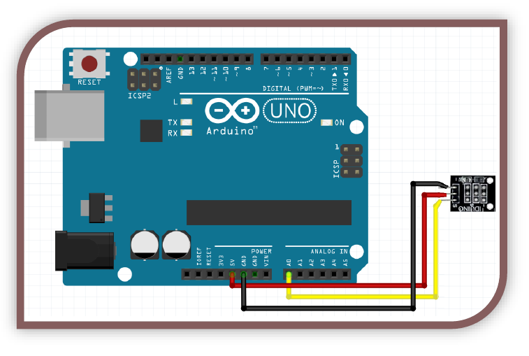
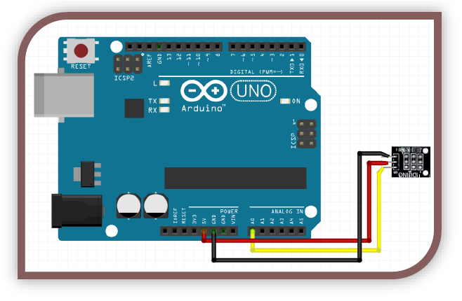
MODULES – Thermistor (Analog temp) Module
Voltage (Min-Max): 3-5V
# of Pins used: 3
Type of pins used: DIGITAL

What IS a Thermistor (Analog temp) Sensor?
A thermistor is a special type of resistor which has a linear and rapid value change based on its temperature. We can read the resistance changes and work out the temperature with some clever math. Instead of spending an hour working the math out using the spec sheet etc, I have used code found on the Arduino forums. This is standard and most people cut and paste code for their first few projects, finally delving in when they feel confident.
Why would I need a Thermistor?
Sometimes you want to know the temperature of an enclosure or perhaps the ambient temperature to automatically adjust values etc. The thermistor is a handy analog package. You can also get digital temperature sensors that output similar values, and digital sensors that you must communicate with using serial protocols. The thermistor is quick and easy, so long as you have the math needed to convert the readings to a temperature!
Example Circuit:
NOTE: In this case, if you find the temperature seems to drop rather than climb when you hold your finger on the sensor, you are in the same boat as me. The assembly crew have put my sensor on the board backwards hehe. Simply swap the red and black wires around and it will be fixed! It is a little amusing to me though, for a moment I thought I was sub-Zero!
Example Code:
//----Begin Code (copy from here)----
//Includes:
#include <math.h> //contains common math functions
//Variables:
void setup() {
// put your setup code here, to run once:
Serial.begin(9600); //Start serial
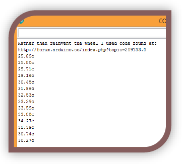
Serial.println("Rather than reinvent the wheel I used code found at: ");
Serial.println("http://forum.arduino.cc/index.php?topic=209133.0");
}
void loop() {
// put your main code here, to run repeatedly:
Serial.print(Thermister(analogRead(A0))); //This is basically saying - first run the Thermister function, passing in the value from the sensor, then print the returned value to the console
Serial.println("c"); //then print the c for celcius, and send a newline character (as denoted by the println rather than print
delay(500); //wait half a second before repeating
}
//custom functions
double Thermister(int RawADC) {
double Temp;
Temp = log(((10240000/RawADC) - 10000));
Temp = 1 / (0.001129148 + (0.000234125 + (0.0000000876741 * Temp * Temp ))* Temp );
Temp = Temp - 273.15;// Convert Kelvin to Celcius
return Temp;
}
//----End Code (copy to here)----
Expected Output:
The expected output is the temperature displayed in the serial window! Touch the sensor with your finger to heat it up and watch the reading rise, then allow it to cool in the air and watch it fall. Blow on it and see if it cools faster!